White Papers
Technology Based Crane Monitoring and Diagnostics
INTRODUCTION
Overhead cranes are often a single source cause of downtime in any manufacturing facility, especially when discussing those performing services in a steel mill’s melt shop. Often, these assets do not have redundancy that would allow for one to be taken offline while the plant is in full production to perform maintenance tasks in cases of emergency breakdowns. Additionally, overhead cranes are some of the hardest assets in a facility to access for maintenance purposes; whether this is for routine preventative maintenance (PM) inspections, predictive maintenance (PdM) testing, troubleshooting, or physical repairs. Therefore, it becomes clear that these assets are some of the most challenging electromechanical systems that our Maintenance & Reliability Departments have to oversee and maintain. Over the years, many advances in technology have opened up new and exciting methods for helping our Maintenance & Reliability Departments with the task of keeping these machines in top operating condition between scheduled outages to maintain production schedules. This paper will subsequently highlight many of these new technologies that are now readily available to end-users and discuss their specific relevance when put into service for crane applications.
DISCUSSION
Conventional / Route Based Vibration Analysis
Though vibration analysis has existed in one form or another since the 1950s, its implementation into the monitoring and diagnostic realm on overhead cranes has been limited at best due to inherent problems associated with collecting the vibration data on these systems. Each crane application will have its unique problems to overcome with regards to the implementation of vibration analysis, but all cranes inherently have the same fundamental challenges in regards to proper vibration analysis data collection for condition monitoring and diagnostic purposes:
- Safety concerns accessing drive components during normal operation
- Significant speed variations with limited steady-state operation durations
- Various loading scenarios with forwarding and reversing rotational directions
- Multiple transient vibration sources
Safe access to a crane during normal operation is by far one of the most difficult hurdles to overcome when utilizing conventional / route-based vibration analysis practices if it can be accomplished at all. Most cranes in the steel industry are very limited to this type of access due to strict safety protocols, and the practice is even forbidden in many circumstances. In these scenarios, the Maintenance & Reliability Departments will have to determine what components on the cranes are deemed critical enough to have this technology added to their routine PM Inspections which typically take place during scheduled outages. By utilizing very strict data collection guidelines, with precise planning and scheduling practices, these limited tests are a viable option for many facilities. Once the list of assets to be monitored is set and a safe access plan has been developed, the next step is to determine data collection protocols.
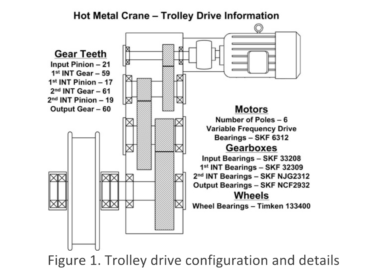
Using standard route-based data collection practices and guidelines, the limited steady-state operation times will dictate the amount of data a technician can collect on each crane component. As an example of these constraints, a collection scenario from an actual application will be reviewed. The crane being used for this discussion is a bridge crane with a 200-ton rated capacity on the main hoist. The specific component targeted for review will be the trolley’s drive assemblies which consist of an AC Induction motor controlled by variable frequency drives (VFDs), directly coupled to a 3 stage gearbox, which is mounted directly to the trolley’s drive wheels (Figure 1). The details of the machine’s mechanical components combined with the available steady-state operation times (Figure 2) will dictate what components can be analyzed using conventional “route-based” data collectors.
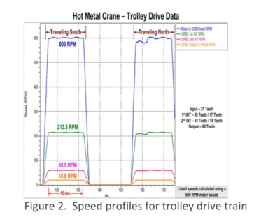
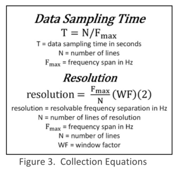
Full travel for the trolley assembly across the bridge’s superstructure on this crane equates to roughly 16 seconds of steady-state operation with the motors running at 600 RPM. The collection time available is a key component when determining vibration analysis setups since the data collection time will vary between each measurement of a system based on the maximum frequency being targeted for analysis and the resolution needed to separate frequencies of interest for defect detection/diagnostics (Figure 3). By targeting each component’s highest and smallest frequency of interests per reading type, one can easily determine which measurements can or cannot be taken utilizing established route-based vibration analysis techniques (Figure 4).
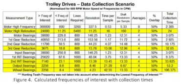
As demonstrated in Figure 4, the trolley drivetrain as a whole cannot successfully be monitored in this way due to the limitations on collection times. Many of the high-speed components can be checked without varying traditional data collection practices such as lowering the lines of resolutions or number of averages, turning off the meter’s autoscale function, changing the % of overlap, etc. Once the machine components have been selected for route-based vibration analysis, the specific test procedures will need to be defined. In the case of most machines, proper loading of the system will be needed to provide useable results for analysis and trending purposes. One of the most significant examples of this would revolve around gear-driven machines, which will account for the majority of the drive systems utilized in crane applications. A prime example of this was isolated in the case of a hoist system (Figure 5) which had severe gearing anomalies that could not be isolated unless near 60% of full load rating was achieved during vibration testing.
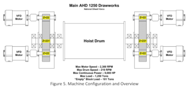
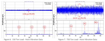
While operating the hoist with roughly a 150-ton load, the resulting vibration analysis signals were relatively low in amplitudes with no obvious frequency-based defect indicators (Figure 6). Additional testing with the load increased to near 750 tons produced significantly higher Overall PK-PK amplitudes in the waveforms and varied frequency distributions in the resulting spectrums (Figure 7). In this example, these key indicators of the machine’s true mechanical health could not have been isolated without adjusting the load to near 60% of the machine’s rated capacity. Additionally, this demonstrates that most mechanical systems’ vibration amplitudes are not linearly linked to their load ratings (increase in load by a factor of 5 produced an Overall PK-PK vibration amplitude increase by a factor of 9.26).
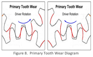
Consideration must also be given to each machine component as to how shaft rotation will affect the measurement results. In the case of many rotational component failure modes (imbalance, misalignment, bearing defects, resonances, etc.) shaft rotational direction will not vary the signal type that indicates a defect is present, but for some crane, specific applications shaft rotational direction is a significant concern. Any gear set being used to transmit power on a crane application will have the unique characteristic of being engaged in the meshing zone on both of the gear tooth faces during normal operation (Figure 8), it is clear that both rotational directions can potentially contain key indicators of gear teeth damage
Lastly, one must contend with the occurrence of transient events that are associated with collecting and analyzing route-based vibration data on crane applications. Simply put, a transient event is an increase in vibration amplitudes lasting only for a short time that is non-periodic in nature. These transient events are most prevalent in the systems associated with the crane rails, such as bridge and trolley drive assemblies. Sources of transient events in these systems can stem from defects or seamed sections in the rails, debris built up on the rails, and even problems with the anti-skewing drive control software that might allow for random wheel flange contact with the railing. While there will be useable data found within the waveforms taken during these transient events, the transient event duration may make FFT analysis of the signal problematic even when proper averaging is performed. As an example of this, two scenarios have been shown in Figure 9 highlighting a long duration transient event (wheel flange rub) compared to relatively shorter duration transient events (rail system anomalies).
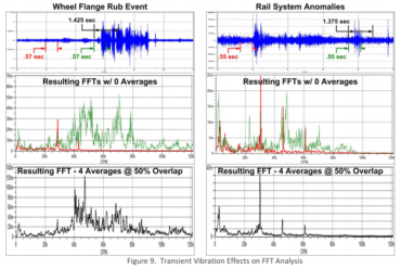
FFT analyses of the signals were performed on the Waveforms at points with and without transient events present utilizing no averaging. The results of these analyses showed the significant differences that the transient events have on both vibration amplitudes and frequency distribution within the resulting FFTs. As a secondary set of tests, the same data was analyzed through the transient events using conventional averaging and overlap settings to generate the FFTs. This demonstrated that the duration of a transient event will significantly change the resulting FFTs even when utilizing conventional averaging and overlap settings for data processing (Figure 4). In cases where the transient anomaly has skewed the resulting FFTs, it will be up to the vibration analyst to acknowledge this deviation from “good” data and then retake the measurement to keep from corrupting the database trends.
Route-Based Transient Vibration Analysis
To overcome the limitations that traditional route-based vibration analysis techniques have had when dealing with crane applications, route-based transient vibration analysis programs have been developed. These programs typically include the utilization of multi-channel dynamic signal analyzers. In years past, these tools were very bulky and would require external power supplies in conjunction with a laptop for control of the system and data storage. As of late, many manufacturers have been developing new systems that are much more portable and do not need external power for field operations. As with traditional route-based vibration analysis, access to the cranes will still be needed to perform transient testing. Strict safety protocols and test guidelines will need to be developed prior to accessing the cranes for testing purposes.
Once access and testing procedures have been made for a specific crane to be analyzed, the mechanical details of each system will need to be reviewed for data collection purposes. Typical crane collection scenarios will include collecting data on the bridge, trolley, and hoist drives. Depending on the data collector being used and the crane specifics, multiple drive assembly components may be collected simultaneously to expedite the collection process and limit the amount of time needed to take the appropriate data for analysis.
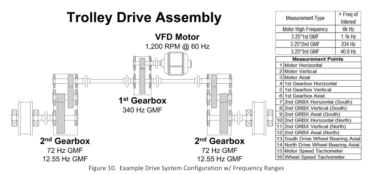
Figure 10 demonstrates a trolley drive that was targeted for routine transient vibration analysis testing. It was determined that the machine’s configuration allowed for a total of 16 synchronous channels of vibration analysis data to be collected with a 6k Hz maximum frequency range. This collection scenario allowed for a single cycle of the trolley from the east-to-west side of the bridge’s superstructure with a return trip to the east location to collect all the necessary vibration and speed reference data required for detailed analysis. In comparison to conventional route-based vibration analysis techniques, it would take multiple round trips to take minimal data on the higher speed components.
By acquiring vibration data in this fashion, the time saved in the field performing the tests will typically be added back to the analysis time required for diagnostics. Typical route-based vibration data will be warehoused in a database with snapshot sections of the waveforms, predefined copies of the resulting FFTs, and various trends available for each measurement taken (Figure 11). Multi-channel transient vibration data is primarily stored outside of the collection software on the computer system’s hard drive as raw waveforms, which have to be imported into additional software packages for analysis (Figure 12).

One of the most obvious limitations found while reviewing transient vibration data is the loss of having the software automatically trend various aspects of the acquired vibration signals. When developing route based transient vibration analysis on cranes, this can be overcome by having a fixed set of routines developed for manually tracking key frequency-based or overall vibration amplitudes with a spreadsheet. This in itself is a very labor-intensive process which will have to be weighed against the expected results over the longevity of the program being developed. As far as comparing the transient vibration data to that of traditional route-based data for true diagnostics purposes, the transient data is far superior in content and usability. Some of the advantages are:
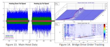
- Continuous data through both directions of travel (Figure 13)
- Order tracking capabilities through speed changes (Figure 14)
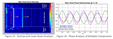
- Startup and coast down data readily available on all data sets (Figure 15)
- Phase analysis across multiple measurements simultaneously (Figure 16)
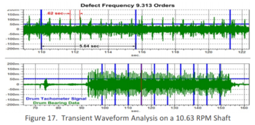
- Transient event analysis with slow speed defect detection capabilities (Figure 17)
Continuous Vibration Monitoring Systems
With ever-increasing capabilities in computer processing, data storage capabilities, and wireless communication technologies, the landscape of continuous vibration monitoring systems is constantly changing. The implementations of these technologies on cranes have been limited at best, but are on the rise as reliability goals and asset management through condition monitoring practices are increased. When looking at crane specific applications, the end-user must first determine what type of continuous monitoring system will fit the requirements for the task at hand since not all monitoring systems are the same. There are three basic types of continuous monitoring possibilities that can be deployed on these assets, each with their unique characteristics and advantages.
- Overall Vibration Amplitude Monitoring Systems
- Bandwidth Vibration Monitoring Systems
- Full Frequency Range Monitoring Systems
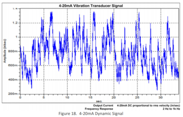
Overall vibration amplitudes have been used to determine machine health in various industrial applications for years through interfaces with a plant’s programmable logic controller (PLC) or distributed control systems (DCS). These simple systems typically involve installing permanently mounted overall vibration transducers (with a fixed frequency range) to key machine component locations, and then having their outputs (typically a 4-20mA signal) go directly into the control system for continuous monitoring. These measurement types are then saved within the system as point values over time, which will produce a trend when looked at historically. Vibration amplitude measurements are then taken at the refresh rate of the PLC’s scanning frequency on a continuous loop, which for crane applications is unreliable since the cranes are not in a constant state of motion. To overcome this hurdle, simple control logic needs to be added to the system that would dictate the collection of the data during ideal states of motion. These simple systems can then be used to generate historical trends that have alert and alarm values associated with each point being monitored. The biggest downfall associated with this type of vibration monitoring would be that there is no useable frequency content stored with the vibration data for diagnostic purposes (Figure 18). Once an alarm status has been met using this system, either a physical inspection of the equipment or additional vibration measurements with a device able to store frequency content will have to be performed to determine the root cause of the increased vibration amplitude.
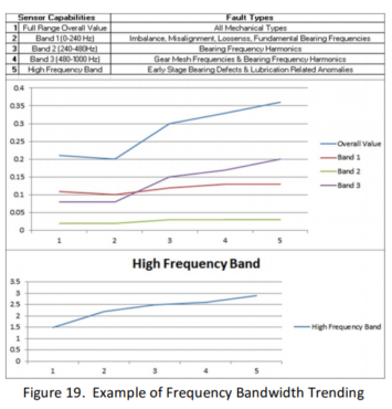
Further developments in transducer design and functionality have further expanded on the old 4-20mA sensor capabilities. These ‘smarter’ transducers can now trend multiple frequency bandwidths, incorporate low and high pass filters, and even incorporate means to trend the highest frequency ranges typically associated with early mechanical failures. A sample of this type of data collection scenario has been provided in Figure 19. This example highlights a system with an increase in overall vibration amplitudes that is specifically linked to the 480-1000 Hz frequency range, with an increase in the high-frequency band which is targeting ultrasonic frequency ranges.
As with the simplest overall vibration amplitude monitoring systems, there is no frequency content stored within this system, but some key factors to the increase in vibration amplitude can be determined. By using the machine’s specific mechanical configurations, each bandwidth will contain specific fault frequency sets that
can be used to aid in data interpretation. For this example, increases in Band 3 are a key indicator of changes in the Gear Mesh Frequency ranges. This with increases in the high-frequency band would allow for the Maintenance and Reliability Departments to plan on performing very specific inspections of the system to confirm the defect types. These inspections could include performing oil analysis on the gearbox, visually inspecting the gear system for signs of wear, or acquiring full-spectrum vibration data on the machine train as means of defect confirmation. This is a significant step up from systems that simply track overall vibration values.
The most current and complete evolution of dedicated continuous vibration monitoring systems has taken the best attributes from traditional route-based vibration analysis and incorporated them into logic-driven systems that can store frequency-based data in conjunction with preset overall and bandwidth alarm parameters. In these systems, the 4-20mA vibration transducers are exchanged for full functioning vibration sensors that are permanently mounted in the field at key locations on the equipment being monitored. Sensor types typically can be matched specifically for each measurement being taken (i.e. proximity probes for sleeve type bearing measurements or accelerometers for gears and rolling element bearings). These sensors will be configured much in the same way as traditional route based systems are, with the added feature of continuous data acquisition capabilities.
Overall and bandwidth alarms are primarily set up for continuous monitoring, with full frequency range data collection reserved for set timed intervals or when predetermined events trigger their acquisition. Recording management becomes one of the key items to review during these system setups in an effort to not fill up valuable memory space with erroneous data that brings no value back to the system’s diagnostic capabilities. In addition to time or event-based data collection, many of these systems also offer the ability to collect long-duration waveforms that can be used in transient analysis. This last feature will further aid in performing detailed diagnostics on a system before physically accessing the crane for review of any alarm scenario or scheduled inspections.
Process Data Acquisition Systems
The next generation of vibration analysis for critical equipment types is the advent of incorporating vibration analysis data into Process Data Acquisition Systems. These systems have been utilized in industry for years to monitor and store process parameters such as temperatures, pressures, flows, forces, and discreet physical locations, and are now being installed on crane applications. The advent of new technologies and desires from industry leaders to include machine condition monitoring data into these systems has made this the newest option available for continuous vibration monitoring. These systems offer a full array of vibration monitoring options which include overall / bandwidth trending, full frequency content monitoring, and transient vibration analysis functionalities.
With the merging of these systems, not only can the crane’s operation parameters be included in the analysis process, more precise vibration data collection trigger events are available for the analyst to utilize. Historically, continuous monitoring systems relied on tachometers or other speed sensors to dictate data collection. Now machine loads, shaft rotational direction, and machine speeds can be utilized to dictate data collection events. These additions to system control help to further refine the vibration data prior to post-processing, which further aids in minimizing file sizes and the amount of data that analysts must interpret to determine machine condition.
Other benefits to these systems revolve around the implementation of process signal analysis for machine condition purposes. With onboard diagnostic tools geared towards analyzing vibration data, the opportunity to review process signals within the same software packages for discreet frequency analysis is now possible, granted that the sensor being targeted for analysis has a useable frequency range that matches the mechanical frequencies of interest. A couple of examples of this type of analysis could be utilizing encoder signals to determine if torsional events are present in a system, or utilizing motor amperage signals to determine if mechanical events are driving minute amplitude changes within a drive assembly.
CONCLUSIONS
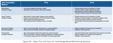
With so many technology-based options now available for monitoring machine condition, it is clear that developing and implementing a system for critical crane applications is now possible. The limiting factors for any technology-based monitoring program developed for crane applications will be heavily dependent on the system expectations from the end-user, the specific crane the technology is being applied to, and the budgetary limitations that will dictate what capital funds are available for the project (Figure 20). As technology continues to advance, its implementation into industrial applications can only be limited by one’s imagination.
You may also like...