About the Author
Jose Luis Rattia
Business Development, RECIP & ROTATING SERVICES CA

I will bring a procedure to diagnostic of misalignment between Engines and Gas compressors this model has their basis in the hypothesis of a point that turns around of a circle, how is showed below; in this figure a, there are two points 1 and 2, this model means that both shaft; engines and compressor should be collinear within conditions of shaft alignment. This model consider the energy accumulated in the points; 1, y 2, this energy can be sensed through a sensor that measure the quantity of energy in both points.
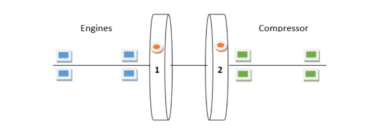
Figure a. Elements to Model of diagnosis misalignment in coupled shafts
For that, we use the correct units to take amplitude of vibration due to forcing force in the coupled shaft to engines and compressor, in this case is selected; Mils P-P, to capture all energy in bearings shell depending what kind of machine be evaluated. We need to draw a line that represent the position of both shaft under conditions of alignment. This model take; 1X and 2X order to plotting the line that say us, in what position is running the shaft to engine and compressor, you can take until 6X to evaluate wear in connrod and main bearings shell under correlation analysis, but at this time we only treat 1X and 2X order to know about misalignment. It is very important to take in account that all collected energy by sensor of vibration permit us identify correct position of common shaft both of them; engine and gas compressor, considering information in 1X and 2X orders. PROCEDURE TO DETECT MISALIGNMENT BETWEEN INTERNAL COMBUSTION ENGINES A
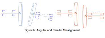
Figure b. Angular and Parallel Misalignment
If both points, 1 and 2, are considered to turns around of coupling circle, you could have a factor called angular velocity that depend of; mass, turning radio, to obtain a value of force in each unit to english or international system. This unit can be related by the expression: F=m.r.w², when you increase radio, then the force increase proportionally. An example of this you can see in the following figure c;
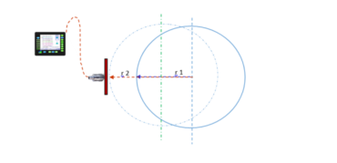
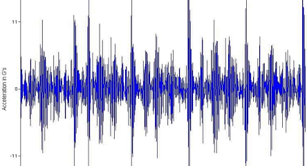
Figure c. Measurement of energy in main bearings with sensor using FFT.
In the figure c; this model present two differents conditions, the first with blue circle fill line, and last one stroke line, the first have r1 how their turning radio, and the Second, have r2 turning radio. The first measurement with r1 hope have less force than second r2. By the way, you could have misalignment conditions generating high rates of wearing in main and connrod bearings to engines and gas compressor under cycle of life to r2. Why this model suppose difference between; 1X and 2X? This model use the differences of fundamental order 1X, in relation to 2X taking in account two elements; inertial force and average changes in the speed due to acceleration when reciprocating mass reach final stroke and both force are opposite.
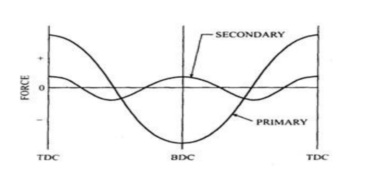
Figure d. Primary and Secondary force opposite at the ending stroke
The figure d; show us, how can be related both forces; primary and secondary forces. In this case, primary force is opposite to secondary force, what represent an arithmetic sum to both values considering their signs; positive and negative. What amplitude unit we can use to monitoring energy in main and connrod bearings? To measuring amplitude of vibrations in main and connrod bearings, you can use; displacement: Mils P-P.
Given that you need plot a line that represents the coupled crankshaft to engine and gas compressor, is required use same units in both case engines and gas compressor measurements. This give us a reliable graph to see profile of misalignment between engine and gas compressor. Now, is time to develop procedure with a spreadsheet to look at complete profile. To do this procedure we use Windrock 6320 PA to take data fft from main and connrod bearings shell in engines and gas compressors. It is very important be clear in your mind what you want to obtain, for that is necessary take data on reliable way to achieve a successful data.
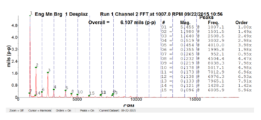
Figure e. Data of FFT main bearings on packages Engine Cat 3612.
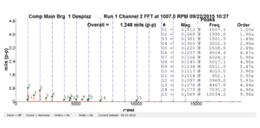
Figure f. Data of FFT main bearings on Compressor Ariel JGC/4.
The datas before showed were collected in a package Caterpillar 3612 with Ariel Gas compressor JGC/4. Coming up next, proceed to create a data table to engine and gas compressor to the seven (7) data collected from main bearings engines and four (4) data from main bearings gas compressor. Here do not be show all data table to engine and gas compressor for space reasons, however same procedure was followed to the others data taken from engine and gas compressor
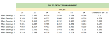
Figure g. Data table to Engine Cat 3612
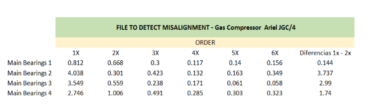
Figure h. Data table Ariel JGC/4
These data were taken directly from software windrock 6320 PA, later these were proposed to organize how a differences between fundamental of run speed 1X, and second order of run speed 2X, getting results up showed.
Then procedure to plot the graph that define profile to misalignment between engines and gas compressor. The graph below, show us; which is the profile followed to shafts coupled in normal operation. The report delivered for technical support after inspection to check alignment condition confirmed; misalignment between engine and gas compressor.
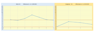
Figure i. Profile to alignment between engine and gas compressor.

Figure j. Technical report from Field service Caterpillar
Conclusions The procedure to detect misalignment in packages internal combustion engines and gas compressors has been until now a practical procedure to identify misalignment and take early corrective actions to guarantee reliability of the package engine and gas compressor during normal operation. Their application do not need stop the machine, besides it permit take control of wearing in engines and gas compressor bearings. The plot line can visualize the profile that could have the engines and gas compressor crankshaft to full load conditions. This procedure is been tested in differents packages units currently in Venezuela, however their application have had successful until now in differents test performed.