
About the Author
Meredith Christman
Product Marketing Manager, PCB Piezotronics

Predictive maintenance techniques have proven to be effective strategies to reduce unexpected machinery failure. Vibration monitoring is by far the most widely used predictive maintenance technology due to the significant amount of machinery condition information provided.
Most plants that implement a vibration monitoring program begin with a portable data collector and a pre- determined route of data collection points. Vibration data is gathered and trended. Maintenance action then is determined based on machinery condition trends. Very often, the new vibration information is reviewed and compared to trended data and no anomalies or exceptions are noted. It is at this point that vibration analysts often realize that they wasted valuable time and resources taking vibration data on healthy machines.
Plant size and the number of measurement points can make implementing a vibration monitoring program a formidable task. Determining the data collection routes and frequency of data collection also can be a difficult undertaking. These issues, as well as having machinery with different rates of failure (ie. the time to machinery failure once excessive vibration is detected), direct many plant managers toward investigating continuous vibration monitoring solutions with permanently-installed instrumentation. These investigations often reveal that most permanently-mounted instrumentation produces a signal that is not compatible with existing plant monitoring instrumentation such as programmable logic controllers (PLCs) and that proprietary, duplicative equipment must be implemented.
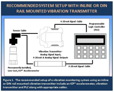
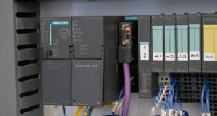
An inline or DIN rail-mounted vibration transmitter (such as Models 682A09 or 682B03) eliminates the need for this duplicative equipment by converting the output of the general purpose ICP® accelerometer (such as Model 603C01) into a 4-20 mA output compatible with a PLC. See Figure 1 for an example setup of such a system. The PLC then could send alarms to the vibration analyst when vibration levels become excessive. These alarms would alert the predictive maintenance team of the need for closer investigation to pinpoint the exact failure mode. That additional analysis is facilitated by a raw vibration signal also available through the vibration transmitter that could be analyzed with portable diagnostic equipment.
This approach is much more cost effective since plant monitoring instrumentation such as PLCs is widely used in many factories. Vibration channels can be added at a fraction of the cost of adding separate redundant vibration monitoring equipment. Other costs, such as installation and training, also are reduced since the monitoring instrumentation already is installed and trained personnel are in place.
Once the decision is made to implement a vibration monitoring program using existing monitoring instrumentation, the next task is to determine the equipment to be monitored and to define the machinery faults that need to be detected.
Answers to the first point are relative to the particular equipment including cost of repair, rate of failure and its importance to the production process. Answers to the second part require a basic understanding of the typical modes of failure of machinery and their respective vibration signatures.
The first step in implementing any vibration monitoring program is to know the equipment. Research the machinery to be monitored in order to be familiar with its operation and understand its potential failure modes.
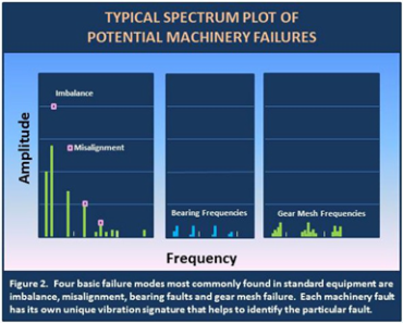
There are many failure modes for machinery. The more complex a piece of equipment, the more complex the failure mode can be. Four basic failure modes most commonly found in standard equipment are imbalance, misalignment, bearing faults and gear mesh failure. Each machinery fault has its own unique vibration signature that helps to identify the particular fault. Each fault has specific fault frequencies that help determine the mode of failure while the amplitude of the vibration helps to determine the severity of the problem.
Imbalance and misalignment most often occur at low frequencies. Mechanical looseness and process loading also can produce faults at low frequencies. These machinery failures demonstrate high vibration at one, two and three times running speed. These low frequencies are typically in the 2-1000 Hz range for equipment operating around 1800 rpm.
Since the mechanical defect is a result of a physically-massive rotor or shaft, the amplitudes are relatively high. A good range for trending vibration is from 0-1 in/sec RMS. Figure 2 shows a basic spectrum plot of potential machinery failures. The units for the frequency and amplitudes have been left off purposely as the actual values would not allow all the faults to be visible in the limited area.
Bearing faults occur at nonsynchronous multiples of machinery turning speed. Specific bearing fault frequencies are unique to the bearings and depend on the physical parameters of the bearings. Specific measurements such as the pitch and diameter of the bearing, the number of balls and the turning speed are all needed to calculate the fault frequencies of bearing failures such as inner race and outer race defects as well as ball bearing defects. Bearing defect frequencies are available from most bearing manufacturers but, as a rule of thumb, one can estimate the frequency by calculating the result of the number of balls in the bearing times the machinery turning speed times 50%.
Vibration amplitudes for these faults are very low as the mass of the moving parts is relatively small compared to the rotor or shaft mass. Bearing fault frequencies range from 200-5000 Hz with relatively low amplitudes. Trending acceleration data instead of velocity data is desired since velocity accentuates the lower frequency vibration and attenuates the higher frequency vibration while acceleration data gives stronger signals at higher frequencies and is better able to measure the lower amplitudes of bearing faults. A typical acceleration range for bearing fault detection may be 0-10 g peak.
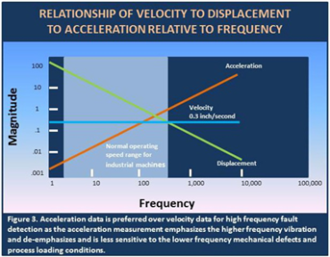
Gear mesh faults occur at higher frequencies than bearing faults. Gear mesh frequencies are the product of the number of teeth times the shaft’s turning speed. Depending on the particular machine, these gear mesh frequencies can range from 100 Hz to over 10,000 Hz. As mentioned previously, acceleration data is preferred over velocity data as the acceleration measurement emphasizes the higher frequency vibration and de-emphasizes and is less sensitive to the lower frequency mechanical defects and process loading conditions. A typical acceleration range for gear mesh fault detection may be 0-50 g peak. Figure 3 shows the simple vibration relationship between velocity, acceleration and displacement over frequency.
As discussed previously, it is imperative to know the machinery in order to effectively implement a vibration monitoring program. Current machinery operating conditions, expected modes of failures and potential machinery faults are all factors to consider when monitoring equipment.
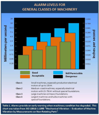
Selecting the proper frequency band to trend relative to the particular fault of interest is critical in order to actually detect the given machinery fault and eventually predict machinery failure. Determining the amplitude ranges within the given frequency band is also important so that alarms will provide an early warning when machinery condition has degraded. Table 1 from ISO 10816-1:1995 “Mechanical Vibration — Evaluation of Machine Vibration by Measurements on Non-Rotating Parts”, show possible alarm levels for general classes of machinery.
Another critical concern for vibration monitoring equipment and alarms is that a time delay be available for each measurement point. A time delay would be used to avoid false alarms that could be set off as a result of transient vibration cause by local traffic, process changes and even ancillary equipment. Also, the time delay should be sufficient to avoid setting off alarms during machinery start up and coast down. During start up and coast down, the equipment could move through mechanical resonances and high amplitude vibrations could be present. Transient time delays should be on the order of 5-10 seconds while time delays for machine start up and coast down should be greater at approximately 1 minute. It may be desirable to de-activate the vibration transmitters and their alarms during start up and coast down to avoid inadvertently setting off alarms.
Summary
Machinery condition monitoring is an important facet in modern maintenance. Avoiding unscheduled downtime is critical to maintain corporate competitiveness. Low-cost condition monitoring of rotating machinery using general purpose ICP® accelerometers (such as Model 603C01), inline or DIN rail- mounted vibration transmitters (such as Models 682A09 or 682B03) and existing plant monitoring instrumentation is an excellent method to gather information to help determine the overall health of a plant’s machinery.


Thanks Meredith, very informative and valuable advice. So I shared on Linkedin my 9k connections.