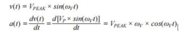
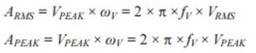
MEMS accelerometers are just now coming of age as vibration sensors in modern condition monitoring (CM) systems. The recent expansion of capability in measurement range, bandwidth, and resolution (noise) is enabling new concepts and system architectures, as CM developers have long awaited the opportunity to leverage the size, cost, and reliability advantages in MEMS sensors. As system architects work through early feasibility studies, some may need to evaluate a particular sensor’s ability to support a range of vibration magnitude (VMIN, VMAX) and frequency (fMIN, fMAX). When the magnitude attributes are in terms of velocity, developers will need to translate them into terms of acceleration, in order to evaluate them against key sensors specifications (noise, range). Equation 1 offers a method for bridging this gap by taking the derivative of a single frequency (fV) model for velocity, V(t), to derive an equivalent acceleration formula, a(t).
Equation 1
The acceleration formula in Equation 1 provides an opportunity to generate simple formulas that relate its peak and rms levels to the equivalent velocity levels (see Equation 2).
Equation 2
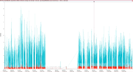
The rms form of these relationships can establish a boundary condition for the accelerometer’s noise by assuming operation through the most stressing part of the system’s vibration boundaries—minimum frequency (fMIN) and magnitude (VMIN). This form of the relationship can be helpful when evaluating a particular accelerometer against industry-standard vibration severity classifications. For example, Equation 3 determines that at a minimum vibration frequency of 10 Hz, the noise in the acceleration measurement must be less than 7.18 mg to detect vibration severity in the good range for a Class 2 machine, per ISO-10816-1 (VMIN = 1.12 mm/sec).
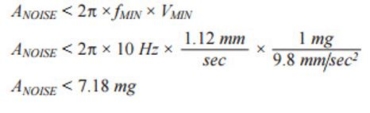
Equation 3
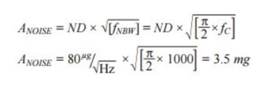
Multiplying an accelerometer’s noise density (ND) by the square root of the noise bandwidth (fNBW) provides a relatively simple method for estimating the total noise in a particular accelerometer and filter configuration.
Equation 4 offers this in a generic form, along with an example, which estimates the total noise associated with an ADXL357 accelerometer (ND = 80 μg/√Hz), when using it with a single-pole, low-pass filter that has a cut off frequency of 1000 Hz (fC = 1000 Hz). At 4.7 mg, the ADXL357 appears to meet the boundary condition from Equation 3.
Equation 4
The peak form of Equation 2 (see Equation 5) provides a tool for estimating another important boundary condition; measurement range in the accelerometer. Equation 5 also presents a specific example, which determines that measuring unacceptable vibration severity on a Class 4 device, per ISO-1081-1 (VMAX = 28 mm/sec), at a frequency of 1000 Hz (fMAX) will require a measurement range of at least ±25.3 g.
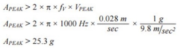
Equation 5
While final sensor selection could require additional consideration and validation, this level of analysis helps assure adherence to the most basic boundary conditions, prior to investing in early test platforms and characterization.