When we were developing our overhead crane monitoring program for ArcelorMittal, we had to find a way to get rid of the influence from the wheel contacting the rails. This is similar to a challenge we encountered when setting up a condition monitoring program for the motors, gearboxes, and wheels of trams.
Measuring Tram Components
De Lijn’s trams did not experience many unexpected outages, but the manufacturers of the gearboxes, the manufacturers of the bearings, and the manufacturers of the wheels and the motors all said the parts needed to be replaced at 50,000 km, 100,000 km, or 300,000 km. But when they did, they saw that most of the repairs were unnecessary. They knew they couldn’t just skip all the preventive maintenance and needed something in place.
First, we installed some sensors close to the bearings and performed some measurements. There was a huge difference between the results when we measured the tram on the tracks and when we measured on the same locations when the bogie was dismantled and driven separately in the workshop. The vast majority of the vibration that we detected was noise coming from the contact between the wheels and the rails.
We decided to set up a measurement program where we could do the measurements in the shop, and this is how we’ve done it for the last ten years for De Lijn and other companies. We measure the trams in the workshop. They are lifted by hydraulic lifts, and that allows us to measure the main wheels as well as the drive motors and gearboxes. This approach has given us good results, allowing us to detect bearing defects in the early stages, and we wait quite a bit longer until we recommend a replacement.
Can We Do the Same with the Cranes?
So that’s how we solved that problem for De Lijn, but the case of Arcelor’s overhead cranes was more difficult. It’s not impossible to lift a crane, it’s very difficult to do it for a large number of cranes in an efficient manner. We decided to try another approach and see if we could get useful readings from measurements taken from cranes on the tracks.
The overhead cranes were 35 m wide and 20 m high and weighed 447 tons. The cranes are lifted when the bearings need to be replaced, but it’s not an efficient option for testing every three or six months.
We had to measure 16 crane wheel bearings (wheel diameter of 1 m) and 8 trolley wheel bearings. The measurement time available for the trolley is less than that of the main bearings because of the shortness of the track. We need decent measurements because the frequency at running speed is quite low. We need at least 20 seconds. That’s easy on the main track
because it’s about 300 m and the speed of the crane is about 6–7 km/h. It takes about two minutes to make the trip. For the trolley, it’s only just enough.
Taking the Measurements
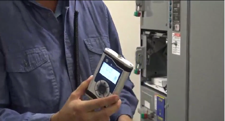
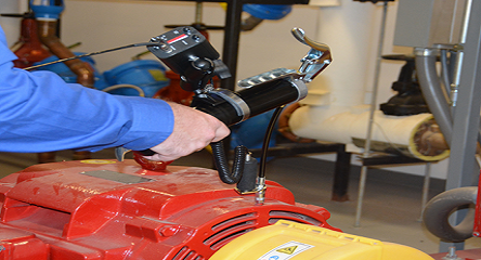
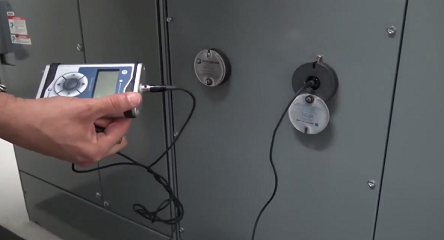
We positioned the accelerometers as close as possible to the wheel bearings. Measurements are made with long cables, so the analysts could remain in a safe location on the crane while it was moving. We usually have one safety man sitting next to the crane operator, and he is in communication with the people locating the sensors and performing the measurements. It’s usually several people taking measurements on one crane.
Standard vibration readings, as we had already seen with De Lijn, would not give us decent results because of the noise of the wheels making contact with the rails. We had to use filters that would only allow the high-frequency vibration through and get rid of all other components. We only want impact signals such as those from outer race defects.
In classic demodulation or enveloping techniques, the signal is rectified and there is an analog waveform obtained by enveloping the rectified signal. This will create a spectrum based on standard sampling. More recent and advanced techniques will do it differently. The first steps are similar, but instead of creating this analog envelope, we do an analog-to-digital conversion using very high sampling techniques. This was first used by CSI in 1994 and they had a 20-year patent on it. Now, similar techniques are being used in different kinds of equipment. High-frequency sampling techniques are the key to these low-speed applications. We have Wi-care products similar to PeakVue that do this.
The Results
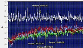
Our first results come from October 2013. We took a standard FFT reading with no filter, and then we used three different filters.
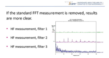
There was a lot of noise in the standard spectrum, which tells us nothing about the condition of the bearing. Filter 3 was a bit too low, leaving most of the noise. Depending on the selection of the filter, we see that these high-frequency measurements may still not be adequate. But if we select the appropriate filter, we get a clear image of any problem. Using Filter 2 we see a nice harmonic family with no clear sidebands, so this was probably an outer race defect.
Notice that if the filter is too high, like Filter 1, we take away the vibration caused by the defect as well. So we need to adjust the filter to obtain a good result.
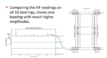
Also, though four sensors were close together on four bearings, only one picked up the defect. This is typical for high-frequency techniques—the information you get is very local. High-frequency vibration doesn’t travel far, so you need to be close to the defect. It’s a disadvantage that you need a lot of sensors, but it also makes it easier to locate your defect. There was no doubt that only the one bearing was damaged and the other three were in good condition.
The analysis is fairly standard. We have a low-frequency spectrum from 0 to 50 Hz. The waveform shows regular periodic impacting corresponding to the BPFO. The frequency itself corresponds to the theoretical bearing frequency. A double-row roller bearing with a shaft diameter of 200 mm. The signature is similar except the amplitudes we encounter here are very low.
This was the first overhead crane we had measured, so we could not compare the situation with others and were working quite blindly. We knew there was something going on, probably an outer race defect, but it was hard to tell whether it was a scratch, a small spall, or a significant defect. We decided to use this as a reference and asked them to replace the bearing.
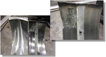
It was not a small defect. The spall reaches the edge of the outer race, increasing the risk of a complete crack. This could have caused an unexpected outage, maybe up to six months later.