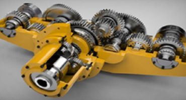
Gear mesh frequency analysis is a key tool for vibration monitoring programs focusing on gearboxes. There are a number of reasons a gearbox may fail including tooth wear, tooth load, gear eccentricity, broken or cracked teeth, gear misalignment and more. All of these failures are preceded by an increased vibration amplitude and will show up in one way or another on a frequency spectrum, though time waveform analysis may sometimes be required to fully identify the root cause. Gear mesh frequency analysis and trending is critical to identifying these faults and diagnosing them before catastrophic failures occur.
Identifying the gear mesh frequency itself is a rather straightforward process using simple calculations, though their complexity can grow depending on the number of stages, or teeth meshes, the gearbox contains. The gear mesh frequency, or GMF, is calculated by multiplying the number of teeth on a gear by the shaft speed:
GMF = (shaft speed) x (# of teeth)
Because gearbox shafts are linked together by design, we can then relate input and output speeds based on the number of teeth using a second equation:
Output speed = Input speed x (Input teeth / Output teeth)
Combining these equations and assigning labels for simplicity, we come to the following:
GMF = S1 x T1 = S2 x T2
Output speed = S2 2= S1 x (T1 / T)
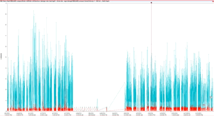
Calculations can be made in terms of CPM/RPM, Hertz, or orders, the latter of which is the most straightforward. Using these equations to calculate the GMF enables a vibration monitoring analyst to track the frequency over time and watch for changes in amplitude that could reflect dangerous operation conditions.
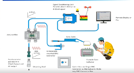
In order to effectively detect the GMF and other offshoot signals, an appropriate sensor needs to be selected. Typically, a 100 mV/g accelerometer can get the job done and provide the bandwidth necessary to cover the GMF and its harmonics, though sometimes a higher sensitivity may be required for extremely low-speed equipment with lower vibration amplitudes. Velocity sensors are another option, but users usually defer to a data collector’s or data acquisition system’s capability to internally integrate the signal from an accelerometer. The exact nature of developing faults may be easily identifiable or might need time waveform analysis to pinpoint but will help guide technicians and analysts to perform the necessary repairs on their equipment before failure occurs.


Excellent Peter.