What is misalignment and what causes it?
System misalignments, as the name suggests, occur when two rotating shafts are not aligned. Figure 1 shows an ideal system where alignment is achieved starting with the motor, then the shaft, the coupling, and all the way to the load (which, in this case, is a pump).
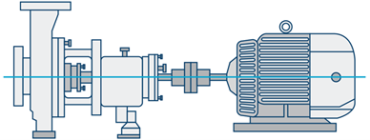
Figure 1. An ideally aligned system.
Misalignments can occur in the parallel direction as well as in the angular direction and can also be a combination of both (see Figure 2). Parallel misalignment occurs when the two shafts are displaced in the horizontal or vertical directions. Angular misalignment occurs when one of the shafts is at an angle relevant to the other.
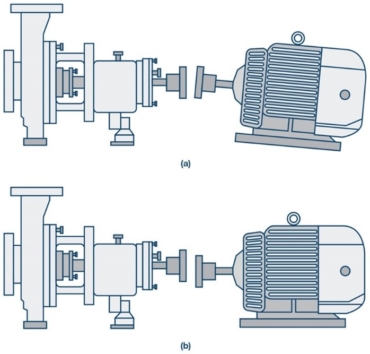
Figure 2: Examples of different misalignments include (a) angular, (b) parallel, or a combination of both.
Why is misalignment a concern?
Misalignment errors can impact the greater system by forcing components to operate under higher stresses, or loads, than what the components were originally designed to handle and can ultimately cause premature failures.
How to detect and diagnose misalignments
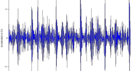
Misalignment errors typically show up as the second harmonic of the rotational rate of the system, referred to as 2×. The 2× component is not always present in the frequency response, but when it is, the relationship of the magnitude to the 1× can be used to determine whether a misalignment is present. Increased misalignments can excite harmonics out to 10× depending on the type of misalignment, the location at which it is measured, and the directional information. Figure 3 highlights the signatures associated with potential misalignment failures.

Figure 3. An increasing 2× harmonic, combined with increasing higher order harmonics, indicates a potential misalignment.
What system specifications must be considered when diagnosing a misaligned system?
Low noise and sufficient resolution are required to detect small misalignments. Machine types, system and process requirements, and rotational rates dictate the allowable misalignment tolerances.
Bandwidth is necessary to capture sufficient frequency range and improve the accuracy and confidence of a diagnosis. The 1× harmonic can be influenced by other system faults, such as misalignment, so analysis of the harmonics of the 1× frequency can help differentiate from other system faults. This is especially true for higher rotational speed machines. As an example, machines operating above 10,000 rpm, such as machine tools, will typically require quality information beyond 2 kHz in order to accurately detect imbalance with high confidence.
Multidirectional information also improves the accuracy of the diagnosis and provides insight into the type of misalignment error and the direction of the misalignment.
The phase of the system, combined with directional vibration information, further improves the diagnostics of a misalignment error. Measuring the vibration at different points on the machine and determining the difference in the phase measurements or across the system provides insights into whether the misalignment is either an angular, parallel, or combination of the two misalignment types.
This tip adapted from the technology article found here.


Good article. In addition to the how many harmonics present in the spectrum. It is important mention is that depend to kind the coupling. For example in the type Gummi coupling , there are 1x and 2X in the Veocity spectrum . the rest of the armonmic are no real, it is for the FFT (Fast Fourier transform)
Regards
GUSTAVO ANTONIO