In May 2015, a K-3603 HHP BOG compressor tripped on high-high radial vibration, exceeding trip setting 83 μm peak to peak as the compressor discharge pressure increased to 68 bars.
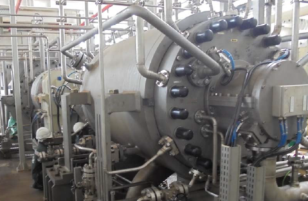
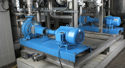
This is a vertical split compressor with back-to-back configuration. The drum in the middle is driven by a gas turbine at 33 MW.
The K-3603 HHP BOG compressor tripped on high-high radial vibration due to radial rub of the rotor against the stator parts (labyrinths and diaphragm), initiated from sub-synchronous vibration. It was eventually overhauled, but that did not work. After it went through another overhaul with swirl brake installation, it passed its verification run.
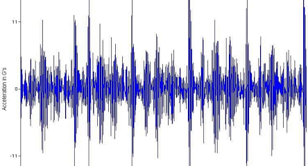
The machine first tripped in May 2015. This spectrum waterfall shows the activity.
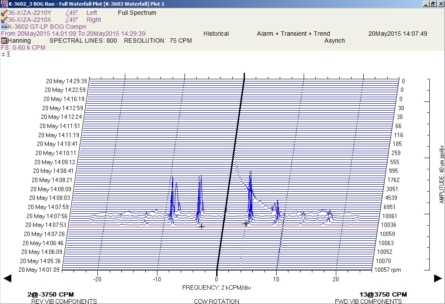
Before the trip, as discharge pressure increased, sub-synchronous started to increase to 13 microns peak-to-peak in the forward direction. Sub-synchronous vibration further escalated in forward and reverse components. As vibration escalated, the sub-synchronous frequency shifted to a higher frequency (from 62.5 Hz to 71 Hz).
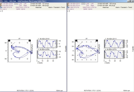
From the shaft centerline, rotor lifting of 10 μm is observed as the vibration level escalates and further lifts up to 60 μm (DE) and 40 μm (NDE) upon compressor trip.
It was time for more tests. OEM insisted that the rotor was stable. Site and shop verifications were conducted. The following tests found no problems or deviations: process parameters/CCC, casing and nozzle deflection, discharge pressure pulsation, and excessive stage temperature. There was deviation in the bearing housing alignment and in the bearing cover clamping.
They found that the DE side bearing support was not in line with OEM limit +/- 0.02 mm. A taper pin had not been properly installed. After reinstalling the taper pin, the bearing support alignment fell within OEM’s limit.
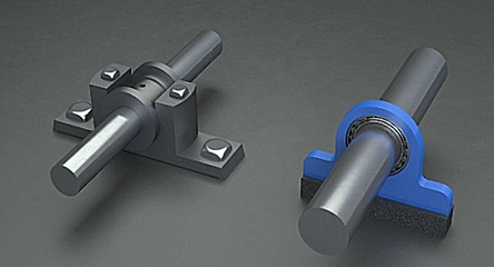
The journal bearings underwent a 3D geometry check.
The original bearing from supplier “A” has a deviation in circularity. The bearing from supplier “B” also had a deviation in circularity but was machined to be within specifications.
The same checks were redone with no conclusive results. Deflector compressor casing, diaphragm, and inner bundle were fine. But the rotor stability analysis was inadequate.
The compressor design was within OEM references. Third-party verification via Software MADYN 2000 V4.0 was done. A swirl brake would increase rotor stability by reducing or eliminating tangential velocity before gas enters the seal. A swirl brake with bearing on pad results in log decrement 0.43 at the worst case scenario.
The running clearance was reduced. A minimum radial clearance of 1.18 mm is based on expansion by centrifugal force and thermal expansion. OEM agreed to reduce the impeller diameter to fall within a safer margin.
As for the final solution, two things were done: reinstatement of specifications and reduction of destabilizing force. The alignment of the bearing pedestal and support was corrected, and they used the bearings from supplier “B” with machining done on pads to ensure circularity. The impeller diameter was reduced by 2 mm to increase rotor and stator clearances. A swirl brake was installed at the suction side of the impeller and balance drum.
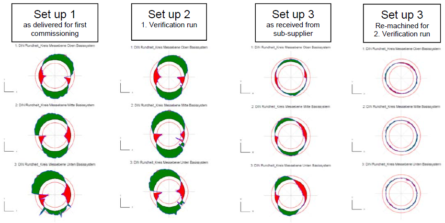
A second verification was done with three types of technology.
- System 1 VMS: Low overall vibration in the range of 10–12 μm p-p with less than 1 μm p-p amplitudes at sub-synchronous frequency
- Casing Vibration Using FFT Analyzer: No vibration at check valve 36-NRV-005 and compressor bearing housing matched frequency of 61.25 Hz
- Thermal Imaging: No significant temperature variant as compressor discharge pressure ramped up to 78.6 bars.
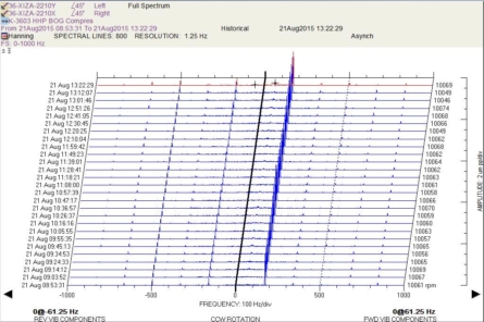
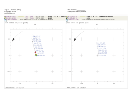
The waterfall plot done during the verification run only shows running frequency.
In conclusion, insufficient damping was provided by the off-spec bearing geometry, which initiated sub-synchronous vibration. There was bearing housing misalignment due to a loose taper, which caused eccentric shaft labyrinth and increased the destabilization force. Any parts could rub during rotor flexing, leading to destabilizing forces that resulted in the decision for impeller trimming. Rotor stability study was valid if components were fabricated and assembled according to specifications. Installation of a swirl brake further improved rotor stability.


Adorei conhecer seu blog, tem muito artigos bem interessantes. anydesk