A guide to using envelope signal processing to pinpoint bearing failure at an early stage.
In any manufacturing or processing plant, machine breakdown has significant consequences. Productivity and profitability are usually affected and there is also a health and safety risk. Surprisingly, however, the cause of the breakdown is rarely identified. Instead, the bearings that were damaged and failed are often simply replaced, in the hope that they may last longer next time.
However, bearings don’t fail without reason. There is always an explanation for why they do, and it is usually for one of a number of reasons: the machine is running unbalanced, misaligned or at a critical speed; a bearing hasn’t been fitted correctly; over- or under-lubrication has occurred; or maybe the wrong lubricant has been used.
Vibration analysis
When problems such as these occur in industrial equipment, sensitive accelerometers are used to detect and analyse the vibrations. This technique is known as vibration analysis and it can identify bearing failure in the very early stages – when there is a microscopic defect on the raceway, for example.
This allows issues to be detected prior to machine breakdown and action can be taken proactively to minimise damage to assets. There is one important problem to note about this technique though: the identifying signal is usually drowned out in all the other noise produced by the machine.
What is acceleration enveloping?
It is vital to catch bearing defects as early as possible, to stop them developing into more serious problems, and one way of achieving this is to use a signal processing technique called acceleration enveloping. It works by progressively filtering out unwanted parts of the vibration spectrum until the signal of a bearing defect can clearly be seen.
Acceleration enveloping is most commonly used in roller bearing systems but can also be applied in areas such as electric motors and gearboxes. It is a key factor in the success of condition-based maintenance (CBM) programmes.
Without acceleration enveloping, maintenance teams and engineers will first learn of damage and failure when overall vibration increases, lubricants are contaminated and temperatures rise. By the time this occurs, the remaining usable life of the failing machine elements could be short and the damage might be more extensive than if any faults had been detected earlier. In worst case scenarios, bearings may fail and the machine could break down before operators notice or resolve problems.
How acceleration enveloping works
Acceleration enveloping is a two-stage process. The first step is to apply a band pass filter to the mix of low and high frequencies of a defective bearing’s unfiltered waveform. This isolates only the frequencies in which the signal of interest is hiding. The filtered output will identify repeating, high-frequency signals. On paper, this process would be represented as a series of spiking energy bursts energy (see the graph below); these are the impacts from the rolling elements hitting the defect of the rotating bearing.
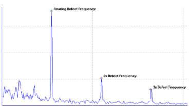
The second step in the process is to pass the filtered output through an enveloper, which rectifies (or demodulates) the waveform, by inverting the negative part to positive and extracts the repetition rate of the energy bursts. This ‘envelope’ is now used as a true vibration signal – helping it to stand out from the noise.
The envelope helps to contain regularly spaced signals, such as a single defect on a raceway, but other causes of noise, such as shaft rub, are random – so will not produce evenly spaced peaks.
It is important to point out that some experience is required to ensure the steps in this process is completed correctly, especially when selecting the correct high- and low-pass frequencies in the first stage of the process.
Acceleration enveloping in action
Acceleration enveloping is most commonly used in roller bearing systems but can also be applied in areas such as electric motors and gearboxes. It has repeatedly proven to be a key factor in the success of condition-based maintenance (CBM) programmes. And while it is predominantly used with signals in the acceleration spectrum, it can also be used to improve other measurements, such as a shock pulse.
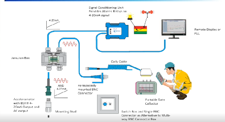
Once the signal has been filtered, the information can be collected from the accelerometer using a data collector, ready for review and interpretation by a specialist. Depending on the data, they can then decide whether or not maintenance work is required immediately, if it can be planned as part of routine schedules, or if no action is required for the time being.
Despite acceleration enveloping appearing to be the definitive answer to detecting bearing failure, it is important to make clear that there are certain times when it might not be the best option. This is because it cannot be universally applied to any machine. The technique detects faults involving repetitive, metal-to-metal interactions. Anything that masks this, such as gaskets or dampers, may put a machine outside its scope of use.
Key factors for success
If an application is suitable for enveloping, several factors will help to ensure the best possible results. Firstly, accelerometers to measure the low-level signal should be selected carefully – in the proper frequency range – to suit the needs of the particular machine or application. There are two main categories of accelerometer, AC and 4-20mA; an experienced provider can assist in selecting the right one for a specific application.
Secondly, accelerometers should then be correctly mounted – close to the component being monitored, on a flat, clean surface to guarantee consistent results. Poor mounting reduces reliability and can make collected data redundant – which means a machine might break down without warning even though it seems healthy and in fine working order.
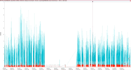
Finally, once accelerometers have been installed and calibrated, data readings should then be taken at regular intervals over a period of time to allow accurate trend analyses to be produced. This allows a steadily deteriorating condition to be identified and for action to be taken before any bearing damage worsens.
It is important to understand that the data and information provided is not a simple ‘yes/no’ answer – and requires some skill and experience to interpret. For example, the amplitude of a worsening condition can reduce over time. A novice might believe this is because wear has stopped. In reality, the imperfection simply becomes slightly smoother and the amplitude reflects that. A specialist would know the problem remains and the condition of the bearing is still deteriorating.
The potential benefits of acceleration enveloping are clear, but it would be unwise to rely on the technique alone. For the best and most reliable data possible, implementing acceleration enveloping, as part of a wider monitoring and analysis regime can be far more effective. This, combined with the information provided within this guide, can help plant engineers to safeguard the health, performance and productivity of all the assets under their care and prevent machine breakdown and lost productivity.
Application example: Acceleration enveloping in wind
The average wind turbine has around 8,000 separate components. Of these, a large number are associated with the drivetrain, which has separately been recognized as the major cause of extended downtime. Wear in gearboxes and bearings, in particular, is known to cause problems and can lead to expensive repairs. Regular vibration monitoring can prevent these issues from occurring.
The complexity of a typical wind turbine does, however, present a challenge for vibration monitoring. Components such as the main turbine, gearbox and generator produce unique vibration signatures, with different amplitudes and frequencies, which can be difficult to isolate from each other and can be masked by noise from surrounding systems. This is where acceleration enveloping plays a crucial role.
To be effective, accelerometers should be fitted to all key rotating parts in a turbine. These include the main bearings, planetary, intermediate and high-speed gear stages, the generator and ideally the nacelle traverse and axial movements. Accelerometers should be selected depending on the frequency of enveloping signals. For example, on wind turbine drivetrains, specifically the generator output shaft, rotational speeds can be relatively slow and may therefore require the use of special-purpose low-frequency AC accelerometers, with a sensitivity of between 100mV/g and 500mV/g.
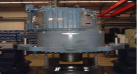
Each accelerometer must be mounted securely on a clean and solid base, and as close to the component being monitored as possible; normally, standard M8 mountings are used. It is also important to collect data regularly and consistently, to enable any change in operating conditions or trends over time to be accurately identified at the earliest possible stage. This can be done on-site using hand held data collectors, which feature software capable of automatically calculating acceleration enveloping, or are transmitted to a remote monitoring centre for subsequent analysis.