About the Author
Meredith Christman
Product Marketing Manager, PCB Piezotronics

The US energy market has experienced significant growth since 2010, transforming from a major fossil fuel importer into a major fossil fuel producer. Fossil fuel (coal, natural gas and petroleum) production has increased by 17% in the last 8 years, driven by developments in shale and offshore extraction.
The American Petroleum Institute (API), the national trade association representing the oil and natural gas industry, affects change in an effort to increase industry safety and influence favorable governmental policy towards the industry. As part of its safety initiatives, the API maintains an extensive standards program that is accredited by the American National Standard Institute (ANSI).
API’s Standard 670: Machinery Protection Systems was created to stipulate the minimum requirements of a machinery protection system in a refinery application in an effort to improve safety, increase uptime and quality and reduce risk. A thorough understanding of the standard can facilitate proper accelerometer selection and field-testing for refinery applications.
Sections 4 and 5 of Standard 670 stipulates several required specifications of accelerometers used in refinery applications. These specifications include:
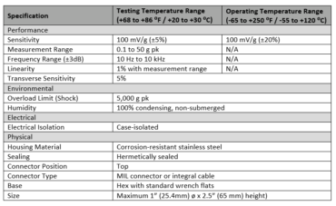
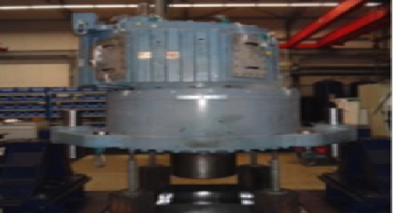
In addition to laying out general accelerometer specifications, Section 5 of the standard provides additional guidelines for casing vibration monitoring of machines with rolling element bearings, including gearboxes, pumps, fans and motors.
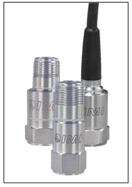
IMI Sensors is one of few accelerometer manufacturers with sensors (Series 622/623/62 8) that meet all of the standard’s requirements.
Construction: Accelerometers from IMI Sensors with a 2-pin MIL or M12 connector have an all-welded design using a hermetic stainless steel enclosure and connector. Every sensor is tested for hermeticity. Due to the design of the sensor and the 100% in- process testing, the individual sensors are considered to have an ingress protection rating of IP68 and are fully-submersible to depths greater than 3 meters.
Calibration: IMI Sensors calibrates every new Series 622/623/628 sensor before it leaves the building in a laboratory accredited by the American Association for Laboratory Accreditation (A2LA) in the field of calibration per ISO 17025:2005, General Requirements for the Competence of Testing and Calibration Laboratories. As a result, full NIST-traceable sweep calibration data with tight sensitivity tolerances and published transverse & linearity specifications are available.
The guidelines for calibrating an industrial piezoelectric sensor are dependent upon the sensing element utilized in the sensor.
In the broadest sense, the calibration process verifies the amplitude response and system linearity over the intended range of use. A typical calibration process is divided into pre-calibration and final calibration.
Pre-calibration consists of, but is not limited to, two tests- a transverse sensitivity test and a resonant frequency test.
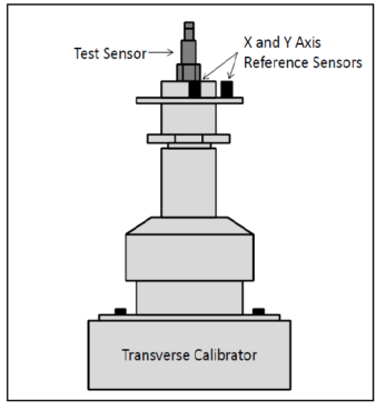
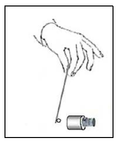
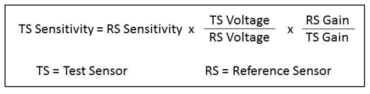
For final calibration, the test sensor is tested in a back-to-back calibration test to determine reference sensitivity, frequency response and output bias voltage. During a back-to-back test, the test sensor is mounted in a back-to-back arrangement with a reference sensor with the reference sensor having traceability to primary calibration. Since the motion input is the same for both sensors, the ratio of their outputs is also the ratio of their sensitivities. The sensitivity of the test sensor can be calculated with the formula below.
 Once the test sensor sensitivity is determined, that sensitivity is then tested at multiple frequencies to develop a sensitivity plot. In the case of a test sensor being tested at multiple frequencies, the calibration service confirms the linear sensitivity response of the test sensor over the useable frequency range during pre-calibration.
Both sensors can be mounted to an electrodynamic shaker driven with a sinusoidal vibration and the sensitivity of the sensor under test is measured at that particular frequency. Sweeping through the desired range of frequencies then generates a frequency response curve of the test sensor. Air bearing shakers are the preferable type of electrodynamic shaker to be used, as they can provide the highest quality of pure single degree of freedom vibration over the widest frequency range, while minimizing the transverse motion and distortion found on other electrodynamic shakers.
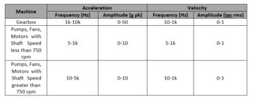
In addition to vendor bench test requirements, the standard also stipulates that a field test of each component of the machinery protection system should be completed by the construction agency on site within the testing temperature range (as specified in the above specifications table) and the subsequent results documented.
Per Section 7.6.2.3 of the standard:
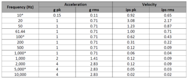
For casing vibration systems, a shaker simultaneously exciting the job accelerometer and a calibrated reference accelerometer shall be used for testing. The accelerometer shall be tested over the frequency and amplitude ranges listed….The monitor system shall be tested to full-scale amplitude by electronic simulation.
The prescribed frequencies and amplitudes are listed in the table below. Frequencies followed by an asterisk are required test points.
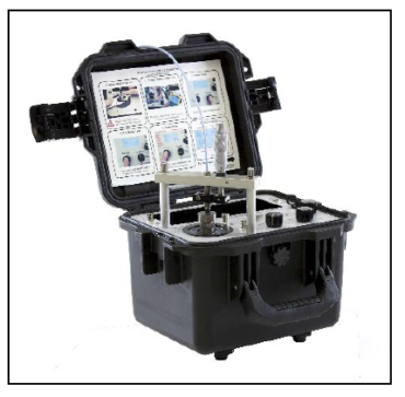
IMI Sensors’ Portable Vibration Calibrator (PVC, Model 699A07) is ideal to satisfy the field-testing requirements of the standard. The unit is a compact, battery-powered and completely self-contained vibration reference source that can be conveniently used to calibrate individual sensors as well as to validate the entire measurement channel of the machinery protection system.
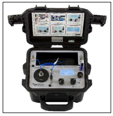
An integral precision quartz reference accelerometer and closed-loop level control gives the PVC enhanced stability and superior vibration calibration over an extended 5 Hz to 10 kHz frequency range. Packaged in a rugged Pelican® Storm case, the PVC is always ready for travel to test sites and bringing laboratory accuracy to the field.
The PVC calculates and displays test sensor sensitivity on the readout screen in real-time. It also has built-in ICP® input for common piezoelectric accelerometers. In addition, users can save up to 500 calibration records directly to the unit’s internal memory. These can also be copied or transferred to the included USB flash drive with Report Generation Workbook via the unit’s USB port. The saved data can then be transferred to a computer and an ISO 17025-compliant customizable Calibration Certificate can be generated and printed.
In addition to being able to calibration IMI Sensors’ accelerometers, the Portable Vibration Calibrator can also calibrate third-party proximity probes per Section 7.6.2.1 with the addition of the optional Proximity Probe Kit (Model 600A22 for an imperial micrometer, Model 600A23 for a metric micrometer). While the standard describes static calibration of a proximity probe, PVC is also capable of dynamic calibration against a 4140 steel target, allowing technicians to simulate actual shaft vibration at turbine running speed, allowing for confirmation of alert and alarm thresholds in the machinery protection system.
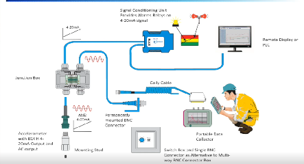
Creating an amplitude linearity calibration certificate while confirming alert and alarm trips at running speed is the most effective method of ensuring correct operation of the machinery protection system. The leading cause of failure in a machinery protection system relying upon proximity probes is cabling. The probe driver converts probe impedance to voltage and produces linear output. It requires precise cable lengths and types typically 1, 5 or 9 meters. Incorrect cabling causes dynamic output from the probe driver to be too high or low, leading to false or late alarm trips.