Validating and troubleshooting vibration sensor setup and performance is an important part of ensuring an effective vibration monitoring system. If a sensor is not working correctly, or if a sensor is not mapped to the correct measurement point, the accuracy of the information is compromised. Sensor functionality is expected, but if there are issues with outputs, there are ways to determine if it is a sensor or installation issue, and if it is either, what might be the root cause.
It all starts with the proper installation of the vibration measurement chain. From the mounting of the vibration sensor to the connection of the sensor to a data collection system, proper setup is vital to the accuracy of the system. The use of tools such as a portable vibration reference source can help ensure confidence in the measurement chain, as well as provide a way to ensure the continued accuracy and performance of sensors and cabling in the field.
Below are some techniques that can be used for sensor validation and/or troubleshooting:
Validating Sensor Installation
Many of us have installed vibration sensors, which include running cables from a sensor at a vibration measurement point on a machine, to an enclosure that will consolidate multiple sensors into a single collection point. If only running a few measurement points, it is usually pretty straightforward and easy to keep track of each sensor. However, if there are multiple measurement points, it is important to ensure that you have mapped the sensor to the measurement point identified on the enclosure. Confidence in the entire measurement chain is the goal of a successful installation. Use of a meter and simply connecting/disconnecting a sensor to ensure the proper measurement point/marking is one way of ensuring connection continuity. A better way to ensure the sensor is working at each measurement point is to use the portable vibration reference to actually generate an input that can be read by the meter to show functionality of the sensor. Another option to validate proper sensor installation is to use the circuitry in some special enclosures that will illuminate if there is a fault in the sensor or the cable upon powering of the circuit with an IEPE power supply, provided by the vibration data collector/logger. If the reading is not what’s expected, the sensor or cable may need replacement. Swapping one or the other out with a known, functional replacement will help confirm where the issue lies.
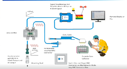
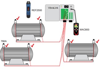
The following is an illustration of how such a sensor validation setup could look – notice how bringing multiple cables into the enclosure could cause some confusion or possible mix-ups!
Sensor Performance Issues
Once sensors are installed properly and their functionality is verified, they should be able to sense vibration accurately for years to come. However, there are various issues that you might run into that require some more advanced troubleshooting. The troubleshooting techniques presented are very simple and can be performed using most monitoring systems and data collectors or simple test equipment. Many installation and sensor problems can be detected by measuring the bias output voltage, or BOV, of the sensor. If the bias voltage is within correct limits the sensor is most likely operating properly. The BOV will indicate faulty cable routes and failed sensors depending on their output, described in further detail below, and many online systems are capable of trending it. Other problems can be detected by analyzing the time waveform and FFT spectrum.
AC Coupling and the DC Bias Voltage
The sensor output is an AC signal proportional to the vibration applied. This AC signal is superimposed on a DC bias voltage, known as the Bias Output Voltage or sometimes rest voltage. The DC component of the signal is generated by the 2mA constant current diode in the power supply. This DC voltage needs to be blocked by a coupling capacitor in the measurement equipment, leaving the AC output signal. Most vibration data collectors, monitors, and sensor power units contain an internal blocking capacitor for AC coupling. If not included, a blocking capacitor must be field installed.
Time Waveform and FFT Spectrum Fault Analysis
The time waveform of a sensor can be measured with an oscilloscope, most data collectors, and online vibration monitoring systems. Reviewing the time waveform can immediately indicate a clipped signal, which usually looks truncated or flattened on one side and normal on the other. Severely clipped signals will cause the waveform to look jumpy. Poor connections can also cause a similar jumpy reading.
The FFT spectrum can give another quick indication of signal quality. The one-times (1X) operating speed vibration, found at the shaft turn rate, is usually present and a good indication of proper operation. The presence of a large ski slope can indicate distortion due to sensor overload. However, a noisy accelerometer that has been integrated to velocity or displacement may also produce ski-slopes for various reasons. Cable routing faults can also be detected by analyzing the FFT. Multiples of the line power frequency usually indicates improper shielding or grounding. If the time and frequency measurements read zero, the sensor is disconnected or is not operating.
Fault indications
Open Bias Fault: Supply Voltage (18 – 30 V)
When the measured BOV equals or is close to the supply voltage, the sensor amplifier is disconnected or reverse powered. In most cases the problem is the connector or cabling. First check the cable termination at the junction box, data collector or monitoring system. If the cable is connected to a terminal block, make sure the wires are secure and in the proper terminal. Next check the cable connection to the sensor. Many times, the sensor was disconnected for maintenance and was never reconnected. If a faulty connector is detected, it can be disassembled or replaced, but avoid disassembling or removing the connector until all other fault sources have been checked. If each end appears good, check all other terminations, splices and connectors. Also ensure that the cable is not crushed or cut.
If the cable route and connections appear good, further test the cable continuity. Cable continuity can be tested by shorting the signal leads at one end of the cable to the shield wire and measuring the opposite end with an ohmmeter. Depending on the cable length, several ohms to no more than several hundred ohms should be measured from each wire to the shield. If the cable and all connections are in proper working order, the fault is in the sensor. However, open faults inside the sensor are very rare.
Short Bias Fault: 0 Volts
When the bias measures 0 volts, power failure or a system short is usually the problem. First ensure that power is turned on and connected. If the power supply is on, check for a short in the cabling. Like the open fault, it is very rare to have a short inside the sensor. The most common fault location is in junction box terminations. Check to make sure that a frayed shield is not shorting across the signal leads. Many times, a crushed cable can produce a short. Use an ohmmeter to check electrical isolation between the leads. Disconnect the cable from all other devices and measure between all signal leads and shields. When measuring the resistance between the cable conductors, the ohmmeter should measure infinite or at least above 50 megaohms.
Damaged Sensor: Low Bias, High Bias
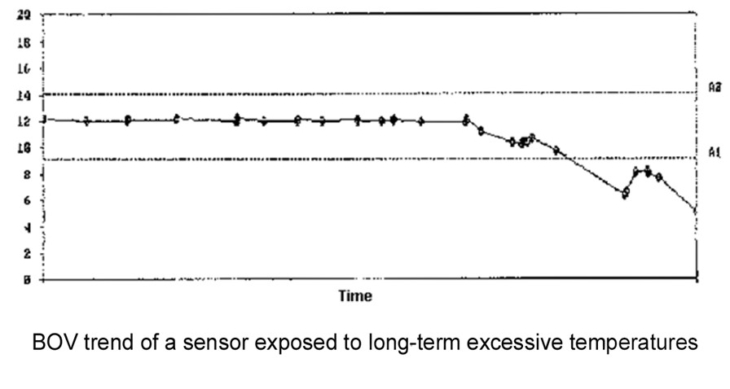
Out-of-specification bias readings other than those listed above usually indicate sensor damage. Common sources of sensor damage are exposure to excessive temperature, shock impacts, mis-powering, and electrostatic discharge. Excessive temperature is the most common cause of sensor failure. Sensors caught in a fire are usually destroyed and can show various bias readings depending on the failure mode within the sensor. Long term temperature failures are marked by a slowly rising or declining bias voltage. In many cases bias returns to normal as the temperature decreases. However, the damage to the amplifier is permanent and it may continue to deteriorate.
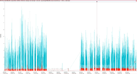
The graph below shows the bias trend of a sensor failing from long term temperature degradation in a paper machine dryer section.
Excessive shock, mis-powering and electrostatic discharge can permanently damage the amplifier of unprotected sensors. Industrial sensors typically contain protection devices to prevent these types of failures, but sometimes can be overwhelmed by outside influences.
Additional Troubleshooting
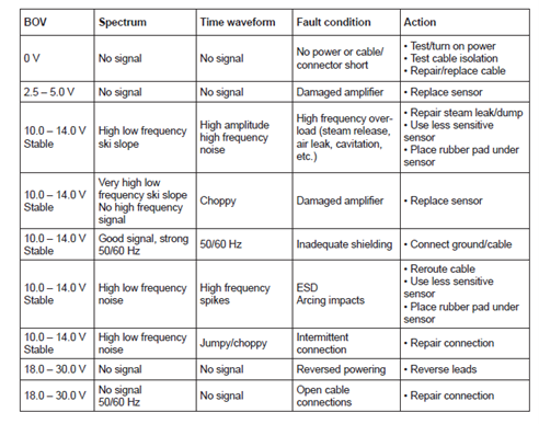
While BOV monitoring is one of the most common ways to determine the status of a sensor functionality, there are times when environmental conditions are the cause of issues. While not covered specifically in this article, below is a troubleshooting matrix that can be referenced for either bias voltage troubleshooting or those more complex issues that you might come across when setting up a vibration sensor network.