Imagine this: you’ve worked hard all of your life, you’ve raised your children, put them through school, and provided a good life for you and your family. Now, you’ve decided to take the vacation that you’ve always dreamed about. You book a cruise for you and your spouse. It’s what you’ve always wanted to do. You set sail, and you’re having a great time. You’re hundreds of miles out at sea and having the time of your life, along with thousands of other people who are also onboard. All of a sudden, there’s a loss of power while you’re having dinner. It’s dark, and the staff begins to reassure everyone that power will be restored momentarily. Hours go by, and still no power.
Temperatures inside the cruise liner begin to rise. There’s no fresh water, and food begins to spoil. All of a sudden, that trip of a lifetime quickly becomes a trip that you wouldn’t wish on your worst enemy.
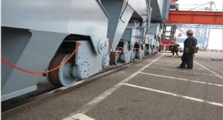
Too often in recent news, we have seen headlines with similar stories of stranded ocean going vessels. Vessels that have become stranded due to failures that could have possibly been detected much earlier through the use of condition monitoring tools such as ultrasound, infrared cameras, vibration analysis, or even oil analysis. The necessary repairs could have then been planned for accordingly, and the repairs made with little to no interruption to passengers or shipping. Condition monitoring tools are widely used throughout various manufacturing plants and facilities world-wide to routinely monitor the health of the assets that are making products, providing utility services, as well as other vital services that many of us take for granted on a daily basis. Cruise ships and other ocean going vessels should be no different, especially when thousands of people’s lives are at risk while hundreds of miles out to sea. Cruise ships aren’t the only ones at risk though. There are literally thousands of vessels crossing our waterways on a daily basis, including off shore oil rigs.
When it comes to condition monitoring tools, one of the most versatile tools available is airborne & structure-borne ultrasound. These hand- held, portable instruments are typically used for applications such as compressed air & gas leak detection, bearing & motor condition monitoring, pumps, gearboxes, and electrical inspection by detecting corona, tracking, and arcing of energized electrical equipment. Other applications that are specific to marine and off shore vessels include diesel engines, steam traps, valves, and hatch/ tightness testing. Ultrasound technology can easily be deployed on ships and other ocean going vessels and can be used while at port or at sea.
How Ultrasound Works
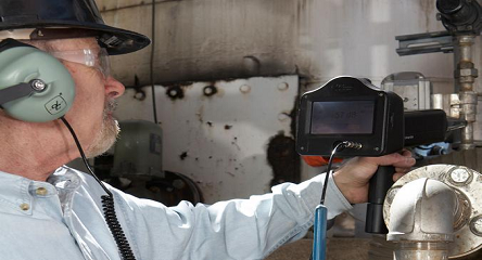
Ultrasonic instruments are listening devices that sense and detect high frequency sound that is normally inaudible to human hearing. The threshold of normal human hearing, that is to say, the maximum frequency at which humans are capable of receiving sounds is around 16kHz to 17kHz. The frequency range of the ultrasonic instrument begins at 20kHz and can be adjusted to 100kHz. So, the instruments are “listening” for sound that is above the range of normal human hearing. Once the instrument detects the ultrasound, it heterodyned or translated by the instrument to an audible sound that is heard through the headset by the person performing the inspection. The sound is also measured by the ultrasonic instrument as a decibel level (dB) which is also displayed onboard the instrument.
The high frequency sound travels via a solid or a gas; therefore, there are airborne ultrasounds and structure-borne or contact ultrasounds. Examples of airborne ultrasounds are compressed air/gas leaks, steam leaks to atmosphere, and electrical inspection of energized electrical equipment. Structure-borne or contact ultrasound inspections would include bearings, gearboxes, pumps, valves, and steam traps. There are also three main sources of ultrasound.
First is turbulence, such as a compressed air/ gas leak. Internal turbulence can also be detected by using the contact approach. For example, turbulence is created when a valve is leaking by. The inspector would make contact on the outlet or discharge side of the valve and would be able to hear the valve leak by. Second is friction. An example of friction producing ultrasound would be a bearing that has a lack of lubrication. Third is ionization. Ionization is produced by electrical discharges such as corona, tracking, and arcing.
Mechanical Inspection with Ultrasound
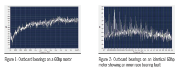
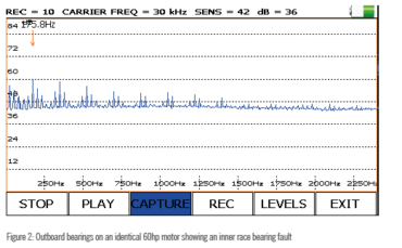
Ultrasound is rapidly becoming the first line of defense tool to inspect and monitor bearings. Ultrasound technology has proven to be very good at finding incipient, or early stage bearing wear and fatigue, thus giving an earlier indication of failure. Even before bearing temperature increases and particle debris discovered during analysis of oil samples. Ultrasound can be used on gearboxes to find faulty gear teeth, pump cavitation, and is very effective on slow speed bearings. For bearings, an indication of bearing failure is noted by an increase in amplitude or decibel level. A bearing that is in a “good” condition will have a much lower decibel level than one that is in a failure mode, such as an inner race or outer race fault. To further aid in diagnosing mechanical problems with ultrasound, instruments with onboard sound recording can be used. Recording the sound of the bearing allows for further diagnosis of the bearing condition through FFT & Time Wave Form analysis. The FFT examples below are a comparison between two identical 60hp motors. Figure 1 is a recording of the bearings on the outboard end of the motor. Figure 2 is recording of the bearings on the outboard end of the motor and shows a very distinct fault harmonic. It was determined that the motor with the fault harmonic had an inner race bearing fault.
The instrument that was used to collect this data also had onboard spectrum analysis capability. The inspector was able to see the FFT and Time Wave Form on the display as the data was collected. Figure 3 is a screen shot from the display of the ultrasonic instrument that also shows the inner race harmonic.
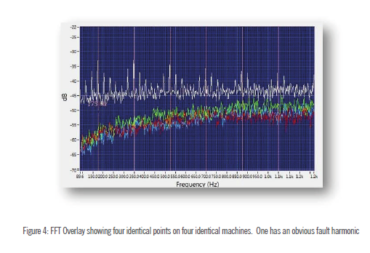
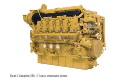
Further comparison can also be done by using the FFT Overlay feature in a spectrum analysis software, such as the Spectralyzer software from UE Systems. The FFT Overlay feature allows the user to have up to four FFT’s displayed on the screen at the same time (Figure 4). This is a great way to compare up to four identical points on four identical machines. Or, to compare a baseline sound file to a recorded ultrasound of when the same point reaches a critical failure mode. Marine type diesel engines (Figure 5) can also be inspected using ultrasound. Both airborne & contact methods can be utilized. Airborne ultrasound inspections on marine engines include compression leaks, leaks on the air intake system such as loose or cracked hoses, small leaks around fittings, and any orifice where turbulence is created by the vacuum created when the engine is in operation. Structure-borne or contact applications for which ultrasound can be used include valves, pistons, cylinders, and solenoids.
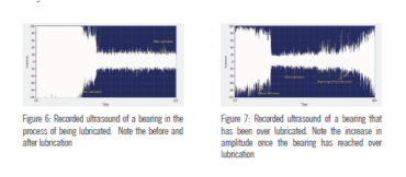
Lubrication issues can also cause failures as well. Studies show that the majority of premature bearing failures can be attributed the lubrication. Whether it’s a lack of lubrication, over lubrication, using the wrong grease for the wrong application, or contaminated/dirty lubricant, all of these are related to lubrication. Ultrasound instruments can be used to listen to bearings while applying lubricant. The source of the ultrasound is friction. When a bearing is in need of lubrication, there is an increase in friction; therefore, an increase in dB. If the inspector is listening and watching the dB while greasing, there will be a gradual drop in dB as grease is applied. Once the dB has dropped back down to a normal level the inspector would stop greasing (Figure 6). In some cases, after the dB has dropped, if another pump of grease is added, the dB may actually start to slowly increase. If this is noted while greasing, the bearing has been sufficiently lubricated. An increase in dB will also be noted if grease is applied to a bearing that is already has enough grease (Figure 7). If grease has been applied, and there is no change in the dB, then a more diagnostic inspection should be performed to determine why the dB did not change. It could be that the bearing is in a failure mode that is beyond a lack of lubrication.
Electrical Inspection with Ultrasound
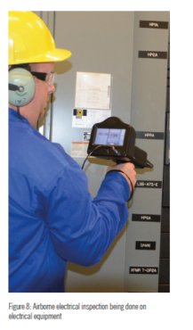
When it comes to electrical inspection, ultrasound instrumentation can be used on almost any energized electrical equipment including metal- clad switchgear, transformers, substations, relays, and motor control centers just to name a few. Ultrasound can be used on low, medium, and high voltage systems. Traditional inspection of energized electrical equipment has been performed by noncontact infrared cameras. However, in recent years, ultrasound has been deployed as an added means of safety. When ultrasound is used, the inspection can be done without opening energized electrical equipment. Since the test is noninvasive, there is a decreased risk of arc flash. If there is a condition such as corona, tracking, or arcing taking place inside of the equipment that is to be inspected, the airborne method is used (Figure 8) to scan any openings on the equipment such as vent opening, louvers, or even the seal around the cabinet door. The ultrasound created from the electrical anomaly inside the equipment will be heard via those openings.
Making use of recorded ultrasounds of electrical anomalies is also very useful, and is the only way to diagnose what is being heard by the inspector. Corona, tracking, and arcing each have distinct characteristics that can be identified in both the FFT and Time Wave Form view in the spectrum analysis software.
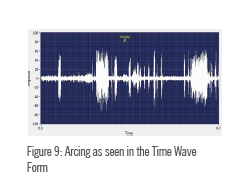
The example below (Figure 9) is from a recorded sound file of arcing which can be described as erratic sudden bursts of electrical energy that is searching for a pathway to ground.
Leak Detection with Ultrasound
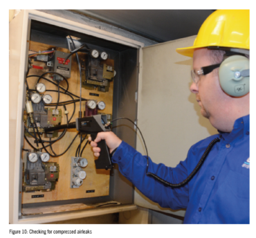
The most widely used application for ultrasound is for compressed air/gas leak detection (Figure 10). It is by far the easiest application for the technology, and there are many benefits associated with using ultrasound for compressed air/gas leak detection. One advantage for using ultrasound for compressed air/ga leak detection is that the inspection can be performed in areas where it is noisy. Since the ultrasound instruments are only listening for the high frequency sound that humans can’t hear, it makes it very easy to locate leaks in areas of high background noise such as engine rooms or mechanical rooms. Leaks as small as 10-2 standard cubic centimeters per second at 5psi can be found using ultrasound.
Marine hatch testing would also be an airborne ultrasound application. With this method, ultrasonic tone generators that emmit ultrasonic signals are placed in strategic areas inside of the bulkhead. The inspector closes and seals the hatch and begins to scan around the seal of the hatch. Anywhere there is a potential for leakage around the seal, the sound from the ultrasonic tone generators that were placed in the bulkhead area will be heard in the headset by the inspector. This is an easy and repeatable test to perform and may even be required by some marine insurance companies.
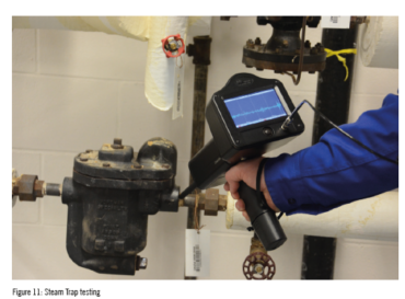
Leak detection applications aren’t just limited to airborne inspections. Structure-borne leak detection includes valves and steam traps as well (Figure 11). When making contact with the outlet or discharge side of a steam trap, the inspector will be able to hear if the steam trap is working properly. When testing steam traps, trap identification is a must. Depending on the type of trap, will determine what the trap is supposed to sound like. A disc trap or an inverted bucket trap condensate inside the trap.
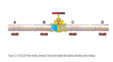
Valve leak detection can also be done with ultrasound. When valves leak or fail, the consequences can be severe in some cases. Especially when safety and energy loss are at risk. Similar to a steam trap, the source of the ultrasound in valve leakage is turbulence. As a fluid or gas moves from the high pressure side of the valve to the low pressure side, turbulence is produced. To inspect a valve, an A,B,C,&D method is recommended. Contact is made at the A point which is slightly upstream of the valve, Point B closer to the inlet side of the valve, Point C close to the outlet side of the valve, and Point D slightly downstream of the valve. The dB values are noted at each of the four points. If the valve is in a leak by condition, there will be a higher dB reading at Point C due to the turbulence created by the high pressure fluid/gas leaking across the valve seat (Figure 12). Point A and Point D readings are taken to ensure that the ultrasound is not coming from either further upstream or downstream of the valve. Time wave form analysis of recorded ultrasounds can also aid in diagnosis.
Conclusion
Airborne & structure-borne ultrasound is a versatile technology that can be used for many marine and offshore applications. Due to its versatility, it is complementary to other technologies that are currently in use on vessels and other marine applications such as vibration analysis and infrared thermography. For areas with little to no accessibility due to safety issues or areas that are just out of reach, remote monitoring can also be done. Remote sensors can be used to connect directly to the hand-held ultrasound instrument, or wired into the ship’s monitoring system. Ultrasound is another tool that can be used to find failures early before they become catastrophic. Additionally, operational impact can also be observed in more efficient planning and scheduling of repairs and in spare parts inventories. When safety and human lives are at risk, finding failures early and making necessary repairs can help to avoid loss of life and the negative press that comes along when things go wrong at sea.