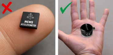
When many people think of a MEMS accelerometer, they think of a MEMS chip. This 2-minute tip will not address MEMS accelerometer chips, which require a pick-n-place machine and soldering to install onto a circuit board and then connection to an output mechanism. We’re going to address mounting an industrial MEMS triaxial accelerometer sensor to achieve the optimal measurement range and accurate readings.
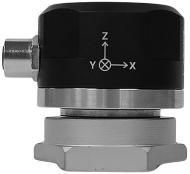
Triaxial orientation
Mounting a triaxial accelerometer may seem less specific than a single-axis sensor, since no matter how you mount the sensor, you’ll get measurements in all three axes. Still, though, you’ll want to be sure of the sensor orientation for consistency in measurements across different mounting locations and accuracy in your documentation.
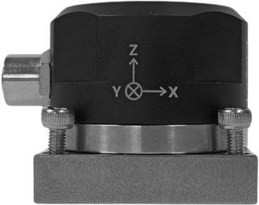
In most cases, the Z-axis will be oriented vertically, through the body of the sensor when sat on a flat surface. The X- and Y-axes then account for horizontal and axial measurements. This should be printed on the sensor for verification. With a digital triaxial sensor, that labeling will be important to cross-check with your data acquisition system and best understand what direction each axis is in reference to. This is especially important when the sensor is mounted on the vertical face of equipment and the Z-axis no longer indicates a truly vertical measurement.
Knowing the ultimate orientation of your sensor and how it will provide data inputs to your monitoring system is crucial in maintaining alignment within your vibration monitoring program.
Other mounting considerations
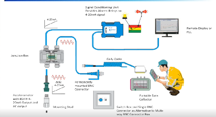
Once the sensor’s ideal orientation is defined, you should follow all the other rules of mounting an industrial accelerometer. The primary consideration is the frequency range of the application. The best method for reliable data collection is threaded mounting, which most closely duplicates the ideal condition of sensor calibration. It allows for the widest dynamic measurement range. Studs or mounting pads are recommended for permanent installations and any time higher frequency vibrations are expected. Threaded mounting requires drilling and tapping a small hole in the machine. Because your X- and Y-axes’ directionality is dependent upon the final orientation of the sensor, it may be necessary to employ specific mounting methods to accomplish the desired outcome.
Stud mounting may not always be sufficient because of how the threads ultimately dictate the final orientation of the sensor body. Your X- and Y-axes may end up several degrees away from their ideal orientations. Captive screws allow for sensor body rotation before performing the final tightening, or a unique mounting plate may be required.
Magnet mounts are usually limited to temporary applications because the decreased contact and stiffness between the sensor and the machine results in a significantly reduced frequency range, typically just a few kHz. The additional mass of the magnet will also contribute to a lower resonant frequency. However, you may want to use a magnet in permanent applications when it is not practical to drill and tap the machine being monitored.
Mounting best practices include spot facing, verifying perpendicularity, and enhancing surface-to-surface contact with coupling fluids. If you want to learn more, see my 5-minute fact Accelerometer Mounting Techniques Impact the Accuracy of Vibration Measurements. Or for a true deep dive, watch our webinar Accelerometer Mounting Techniques for Reliable Measurements.