White Papers  

Making It In A High Frequency World

Meredith Christman | Product Marketing Manager, PCB Piezotronics

MAKING IT IN A HIGH FREQUENCY WORLD

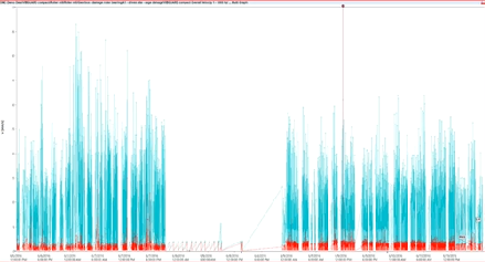
As predictive maintenance teams in industrial facilities strive for a more complete picture of their equipment’s health, high frequency vibration measurements have become a crucial addition to identify faults such as motor and pump bearing defects and gear tooth inconsistencies in high-speed gearboxes. As a result, there is an upsurge in demand for vibration sensors with a high frequency response.

Hooke’s Law and the Spring-Mass Harmonic Isolator

What determines the resonant frequency (and therefore high frequency response) of an accelerometer? For that answer, a look into the field of physics and the spring- mass harmonic isolator are required.

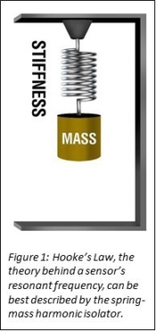
A spring-mass harmonic isolator consists of a spring hung vertically from a support structure. A weight is attached to the end of the spring. By pulling the weight down and then releasing, the weight/spring assembly will oscillate evenly (both in speed and distance) back and forth across an equilibrium position, re-creating the oscillation of a sinusoidal wave.

While the amplitude of the resulting oscillations can be theorized using Newton’s Second Law of Motion (F=ma), the primary interest of this article is the speed of the resulting oscillations. The speed of the resulting oscillations can be theorized using Hooke’s Law (Robert Hooke, late 1670s). Hooke proclaimed that natural/resonant frequency is a function of stiffness and mass, as seen in the formula below. In the spring-mass harmonic isolator example, the mass of the weight and the stiffness of the spring are pre-determined so the assembly’s oscillation speed cannot be altered unless either the spring or the weight are switched out for an alternative.

Based on the formula above, it can be seen that resonant frequency and mass have an inverse relationship while resonant frequency and stiffness have a direct relationship. In the world of accelerometers, the mass of the weight correlates to the mass of the accelerometer while the stiffness of the spring correlates to the stiffness of the accelerometer’s mounting. To achieve high frequency measurements, an accelerometer must be as small as possible and have as stiff of a mounting methodology as possible. Each of these two factors are explored in detail in the following sections.

Factor #1: Stiffness of Sensor Mounting Methodology

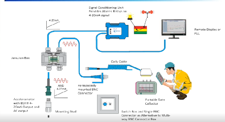
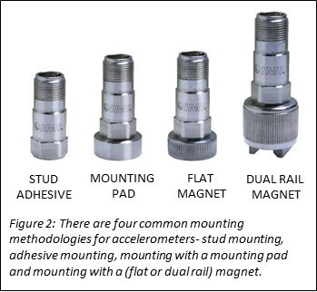
There are several common methodologies used for vibration sensor mounting. These include stud mounting, adhesive mounting, use of a mounting pad and use of a magnet. The characteristics of each mounting methodology are described below.

  • Stud Mounting
    • Maximum Frequency Response: Stud- mounting an accelerometer directly to a piece of equipment provides the stiffest possible mounting and therefore the highest possible frequency response from the sensor.
    • Equipment Modifications/Permanency of Installation: To stud-mount a sensor to equipment, it is necessary to spot face a smooth surface and then tap a pilot hole to fit the sensor’s mounting thread. Once removed, there is still lingering evidence of the past sensor mounting.
    • Can Install on Curved Surfaces: Stud mounting a sensor on a curved surface is not possible.
  • Adhesive Mounting
    • Maximum Frequency Response: Mounting an accelerometer with adhesive directly to the equipment provides the second stiffest mounting methodology. Frequency response is reduced only slightly (approximately 10-15%) compared to a stud- mounted accelerometer.
  • Equipment Modifications/Permanency of Installation: An adhesive-mounted accelerometer can easily be removed with the appropriate dissolving agent for the adhesive. Once removed, there is no evidence of the past sensor
  • Can Install on Curved Surfaces: Adhesive mounting a sensor on a curved surface is not possible
  • Mounting with a Mounting Pad
    • Maximum Frequency Response: Mounting pads can be adhesively bonded or welded to an equipment surface. The sensor can then be stud-mounted to the mounting pad via the tapped hole in the pad. This type of sensor mounting is considered a midway point between the stiff methodology of stud mounting and the flexible methodology of magnet mounting. Frequency response will be reduced by approximately 35% compared to stud
    • Equipment Modifications/Permanency of Installation: While a weld-mounted pad is a relatively permanent installation, an adhesive mounted mounting pad can be easily removed with the use of an appropriate dissolving agent for the
    • Can Install on Curved Surfaces: Mounting a sensor on a curved surface with a mounting pad is not possible.
  • Mounting with a Magnet
    • Maximum Frequency Response: Mounting an accelerometer with a magnet is a very flexible mounting methodology that will significantly degrade the sensor’s high frequency response by as much as 80-85%.
    • Equipment Modifications/Permanency of Installation: The lack of required equipment modifications and the temporary nature of the installation are the reasons why magnet mounting is used in many applications. Magnet mounting offers the most convenient method of temporary sensor installation for route-based measurements and data
    • Can Install on Curved Surfaces: Magnet mounting a sensor on a curved surface is possible when a dual rail magnet is used

Factor #2: Sensor Mass

Sensor manufacturers continue to make smaller and smaller accelerometers in order to satisfy customers’ requests for sensors capable of high frequency measurements. This effort is challenging as they must balance the small size with the need for a rugged sensor that can withstand the harsh environments to which they are usually subjected.

Most industrial customers require:

  • Robust Housing: In the world of industrial accelerometers, the robustness of the sensor’s housing is not determined by one single factor. It is determined by the housing material, the level of sealedness that the housing provides and the electrical isolation of the housing. Most industrial accelerometer housing are 304 or 316 stainless steel and hermetically sealed in order to withstand chemical exposure and wide operating temperature ranges. A case-isolated housing allows an accelerometer to be mounted on equipment with poor electrical grounding without running the risk of signal contamination. The isolation is typically achieved with the use of a Faraday cage, a continuous enclosure around the sensor’s electronics to repel noise
  • Rugged Connectors: Connectors must be able to withstand repeated use in harsh conditions. Military-style connectors are preferred as they can withstand extreme conditions, as can their mating cables.

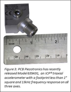
Despite the challenges, sensor manufacturers like PCB Piezotronics, Inc. have been able to successfully shrink the size of industrial accelerometers to a size close to that of a quarter. Their newest high frequency model, Model 639A91, is a triaxial ICP® accelerometer that measures just 0.95 inch by 0.95 inch (excluding the side exit connector) and features a 13 kHz frequency response on all three axes. It features a case-isolated housing of 316L stainless steel and rugged four- pin M12 connector.

Conclusion

High frequency measurements are gaining prominence with industrial predictive maintenance teams as they strive to have the most complete picture possible of a piece of equipment’s health. The size of the sensor and the stiffness of sensor mounting methodology are the two most important factors contributing to a sensor’s ability to successfully provide high frequency measurements.

Subscribe
Notify of
guest

This site uses Akismet to reduce spam. Learn how your comment data is processed.

0 Comments
Inline Feedbacks
View all comments

About the Author

Meredith Christman Product Marketing Manager, PCB Piezotronics