General Computer Program for Two-Plane Balancing of Rigid Rotors
-
Overview
Due to the cross-effect, the two-plane balancing of a rigid rotor is advisable. The standard solution is used for a center-hung rotor, and the static-couple effective solution is employed for an overhung rotor [1,2,3,4]. All of the variables for the program have been completely defined, and the appropriate two-plane balancing procedures for center-hung and overhung rotors have been also explained [1,2,3,4]. For a frontal observer of the rigid rotor the location of the near, N, and far, F, bearings is relative, but the position of the left, L, and right, R, planes does not change, and this fact must be considered for the correct application of the corresponding balancing method to rotative machinery [3].
The program was checked from previous results [1,4] and from new experimental data by means of the online software for the two-plane balance of rotating machinery, developed for the lead phase measuring system with the rotating scale convention [5], avoiding a paradox if the trial weights are attached at 0 or 180 degrees [1], as well as by the two-plane balance program developed for the lead phase measuring system with the fixed-scale convention [2, 6] and utilized for the lag phase measuring system with the rotating scale convention [4].
-
Development
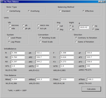
First of all, the Rotor Type (Centerhung or Overhung) and the Balancing Method (Standard or Effective) must be recorded. The program asks the user for the Units of vibration (Vib) with the corresponding angle (Ang) of weight (Wght) and frequency including its value f. The program requires the method for measuring angles, specifically the phase measurement System (Lead Phase or Lag Phase), the phase Convention (if the angles are measured on the inner Rotating Scale or on the outer Fixed Scale) and the scale Direction (if the angles are measured: in the Same rotor’s direction of Rotation or Contrary to the rotor’s direction of Rotation) In practice the question is: if the protractor’s angular scale coincides with the rotor’s direction of rotation or if it is opposite to the rotor’s direction of rotation. Regarding the Balancing Equipment, in the case of the Lead Phase measuring system the stroboscope and the photocell give identical values for the phase angle, but in the case of the Lag Phase measuring system the phase angle is measured using the photocell and its value is independent of the direction of rotation. However, the stroboscope synchronized by the sensor can be used for the Lag Phase with the Fixed Scale Contrary to Rotation or with the Rotating Scale in the Same rotor’s direction of Rotation. The following combinations produce an angle, ang, in a direction contrary to rotation: {(Lead Phase AND Rotating Scale AND Contrary to Rotation) OR (Lead Phase AND Rotating Scale AND Same of Rotation) OR (Lag Phase AND Rotating Scale OR Fixed Scale AND Same of Rotation)}. The following combinations produce an angle, ang’ = 360° – ang = – ang, in the same direction of rotation: {(Lead Phase AND Fixed Scale AND Same of Rotation) OR (Lead Phase AND Fixed Scale AND Contrary to Rotation) OR (Lag Phase AND Rotating Scale OR Fixed Scale AND Contrary to Rotation)}. IF any of the preceding combinations occurs THEN the complex conjugate of the vector operators or vector factors (VL, aVL) and (VR, aVR), in its respective coordinate system must be taken [1,2,4]. Figure 1(a) will help to understand each one of the combinations, and Figure 1(b) shows the vibration vectors, (vib, ang) in the coordinate system (x, y) and (vib, ang’) in the coordinate system (x,y’), for both sets of combinations. According to the experts, the phase angle convention can be extremely confusing, and the lead phase system was not considered [7] (here as lag phase system). The algorithm explained in this paper details for maintenance engineers the system and convention for phase measurement.
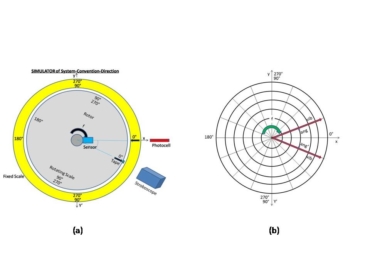 Figure 1. (a) Image produced by stroboscope, (b) Vibration vectors in the coordinate systems.
The effect of the trial weights, (WTL,aWTL) and/or (WTR,aWTR), on the bearings’ vibration, (N,aN) and (F,aF), allows the program to Calculate the Initial Balance,(WL,aWL) and (WR,aWR), and from the remaining bearings’ vibration, (NRem,aNRem) and (FRem,aFRem), the necessary additional or Trim Balance, or determines the residual unbalance [4], giving results in polar coordinates for each case.
The listing of the new source code is written in Lazarus (Free Object Pascalsimilar to Delphi)[8] for a computer Dell (Intel Core 2Duo 3 GHz, RAM memory 2 GB, Hard Disk 160 GB, Windows 7 Starter) with a monitor Samsung (Model SyncMaster 920LM) as follows:
{Two Plane Balancing of Rigid Rotors General Computer Program}
With the following results:
3. Conclusion
A general computer program for two-plane balancing of rigid rotors has been developed, which is useful for different instruments with particular measuring systems and phase conventions.
References
- José A. Méndez-Adriani, “Considerations on the Field Balancing of the Overhung Rigid Rotors”, The Shock and Vibration Digest, Volume 37 – Number 3, May 2005, pp. 179-187, SAGE Publications.
- José A. Méndez-Adriani, “Rigid Rotor Two-Plane Balancing Solution for the Fixed Scale Convention”, Conference Proceedings of the Vibration Institute, presented in Jacksonville, Florida, USA, June 19-21, 2013, 8 pp.
- José A. Méndez-Adriani., “Invariance of Vector Factors in the Direct Solution for Two-Plane Field Balancing with the Orientation of the Overhung Rigid Rotor”, Uptime Magazine, February/March 2015, pp. 62-64.http://www.reliabilityweb.com
- José A. Méndez-Adriani, “A Two-Plane Balancing Solution for the Lag Phase Measuring System”, Uptime Magazine, October/November, 2016, pp. 52-55. http://www.reliabilityweb.com
- llc, Rotor Two Plane Balancing, Machine Maintenance, http://www.denysschen.com/Balancing/WebBalance/2PlaneBalance.aspx, 2019.
- IRD Mechanalysis, Balancing Systems Division, Balance Programs, Version 1.03.
- Ray Kelm, Dustin Pavelek and Walter Kelm, “Rotor Balancing Tutorial”, 45th Turbomachinery & 32nd Pump Symposia, Houston, Texas, September 12-15, 2016, p. 25.
- Lazarus Team, Lazarus: The Professional Free Pascal RAD IDE, Version 1.8.2, 2018, URL°http://www.lazarus-ide.org, RRID:SCR_014362.


If the direction of rotation is counter clock wise then turn Figure 1 vertically.
Hello Prof Adriani, may you share the balancing system developed by you? Kind Regards.