In this article, we are going to take a look at a fault on an electric motor and then attempt to explain why the vibration changed in the way that it did. First, let’s take a look at the motor from a steel plant in India.
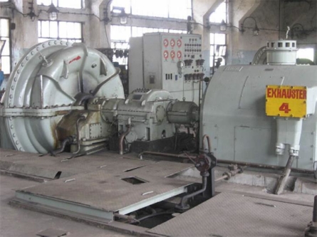
It is a four-pole AC induction motor running at 1500 rpm supported by sleeve bearings. The motor drives a gas exhauster through a speed-increasing gearbox.
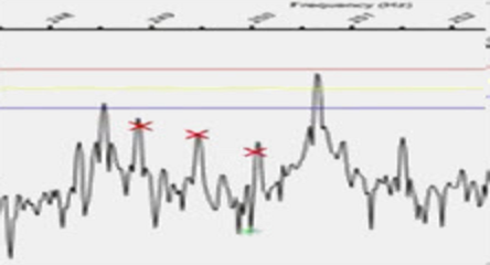
I was sent some spectra and asked to explain why the vibration changed. You can see the spectra below taken with a Fmax of 30,000 CPM. Clearly, there are a series of 1X harmonics. What do you think that means?
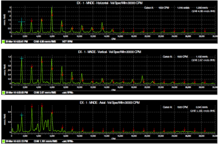
Of course, it is looseness. Or could it be something else? Let’s find out before we jump to conclusions.
I asked for a high-resolution spectrum with a lower Fmax to be taken as this was not normally collected as part of the route. The spectrum below has a Fmax of 12,000 CPM and with 6400 lines. You can now see that those peaks we saw are not simple peaks – they are broad because of the sidebands surrounding each of the peaks. With limited resolution, there is no way to tell that those sidebands are present.
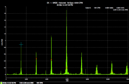
Here is a close-up of the first four harmonics.
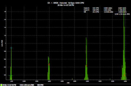
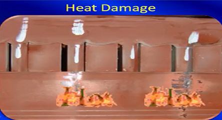
So now what do you think the fault condition is? Well, I thought there must be a broken rotor bar or damaged end rings or some sort of fault of that nature. In other words, the current was not able to flow through the rotor bars properly. There was either a high level of resistance or a break that did not allow current to flow through the rotor bar at all. Unfortunately, it was not possible to take a motor current signature because that would have told us exactly what was happening. If you are not sure what I mean, then you will enjoy the rest of this article.
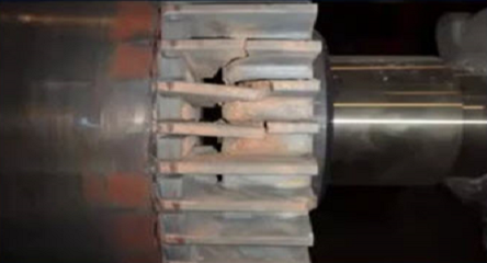
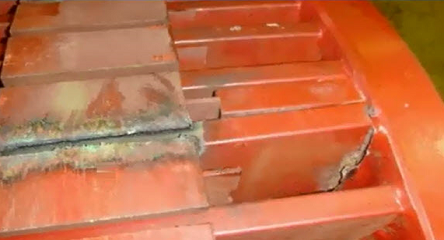
Anyway, I emailed my suggestion to my friend in India and they decided to stop the motor and check the rotor. You can see the photos below.
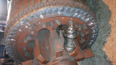
It is pretty easy to see the damage which obviously needed to be corrected.
That’s a pretty quick case study, but as always with vibration analysis, you have two choices of how you treat vibration patterns like this one. You can simply remember that sidebands sitting around the first few harmonics of running speed represent a broken rotor bar (or some other damage that relates to current flow through the rotor bars) or you can attempt to understand what is actually happening and therefore understand why the sidebands appear (and be better prepared for this and other induction motor fault conditions).
Let’s try to do that. Let’s climb inside the electric motor, experience the magnetic field, and figure out why we are experiencing amplitude modulation (after all, that’s why we see the sidebands).
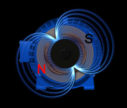
The first thing that you need to understand about an induction motor is that the stator is actually spinning. Well, not physically, but magnetically. If you have a two-pole motor then the magnetic field spins at 3000 RPM. If we had more time I would explain exactly why that is, but in this short article, I am going to ask you to take my word for it. But you can think of the stator of an induction motor as a spinning magnet. It is a two-pole magnet (because it’s a two pole motor) and therefore you can imagine a North and South pole spinning round and round at 3000 RPM. Our motor was a four pole induction motor, so it spins at 1500 RPM. That is its synchronous speed.
The magnetic field was created because an AC voltage (which is a sine wave) was applied to a set of windings. Think of the windings as just a coil of wire, or a solenoid. When a fluctuating voltage source is applied to a solenoid, a magnetic field is created. But it turns out that if you put a coil of wire near a fluctuating magnetic field, current will be induced in that coil of wire. The fluctuation is due to the AC voltage, which is sinusoidal – it rises and falls 50 times per second (or 60 times per second in the US and some other places) – or whatever the VFD feeds top the motor.
So imagine, if you will, a stator with voltage applied, but without a rotor installed. If you were to insert a compass where the rotor should go, the needle of the compass would spin at the synchronous speed (a compass needle is a magnet – it has a North Pole at one end and a South pole at the other end).

But it is a very strong magnetic field. So if we replaced the compass with a coil of wire it would experience that strong magnetic field and current would be induced in that coil. And what happens when current flows through a coil? That’s right, we generate a magnetic field. But that magnetic field will be attracted by the rotating magnetic field that surrounds it – so it spins. And that is how the motor works – you can think of the rotor as just another coil or solenoid with a current induced in it (that’s why it is called an induction motor).
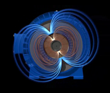
As current flows through the rotor creating a magnetic field it will spin because the North and South pole of the rotor will chase the rotating magnetic field. But what do you think would happen if the rotor was spinning at the same speed as the stator’s rotating magnetic field; i.e. at the synchronous speed? From the rotor’s point of view, it is no longer in a fluctuating magnetic field because it is spinning at the same speed as the magnetic field. And therefore current is no longer induced in the rotor and there is no longer a magnetic field – so it slows down. But as it slows down it then experiences the rotating magnetic field again. When the difference between the speed of the rotating magnetic field and the rotor are similar only a small current is induced and a weaker magnetic field is generated. And that actually explains a few things that we witness with induction motors:
- The rotor spins slower than the synchronous speed. The difference is called the slip frequency.
- If there is greater load on the rotor the slip frequency will be greater because you need more current flowing through the rotor to generate a sufficiently strong magnetic field to spin the heavily loaded rotor
- You have to have a load on a rotor in order to test for broken rotor bars – without the load, there will be barely any current flowing through the rotor bars (and there will be very little slip)
- When a motor is started the currents are very strong until the rotor “catches up” to the rotating magnetic field. They are called the “inrush” currents. That’s why motors that stop and start frequently are more likely to develop rotor bar and end ring problems, and why VFDs are often used to “soft start” a motor (they gradually increase the speed of the rotating magnetic field).
So now we know more about stators, rotors, slip frequencies and magnetic fields. But why do we see amplitude modulation – I think that was the question I posted quite a few paragraphs ago 😉
Imagine you are a rotor bar spinning slightly slower than the rotating magnetic field. To keep it simple, imagine the rotating magnetic field is actually a spinning magnet, with a great big North pole on one side of the motor and a great big South pole opposite it – but spinning at synchronous speed. Because you are spinning slower than the magnet there would be a time when you are directly under the North pole or South pole. At that time you experience the strongest magnetic field. But at another time you are equidistant from the North and South pole and that’s when the magnetic field is weakest.
And how long does it take to get from under the North pole all the way around so you are under the North pole again? Is it the synchronous frequency? No. Is it the rotational speed? No. It is the slip frequency. If the slip frequency was 1 Hz then once per second you would be under the North pole. But how often are you under one of the poles, where the field strength is highest? Twice per second – for a two pole motor. And four times per second for a four pole motor.
If you are a healthy rotor bar, and the current has little resistance between you and the end ring, then while you would feel a rise and fall in field strength, there is always another healthy rotor bar in the strongest part of the field, and all is well.
But what would happen if you were not healthy? What if the current could not flow through you properly? Now there would be a disruption in the normal pattern of things. Each time you pass under a pole there would be a fluctuation. And there, at last, is the source of vibration we measure. The rise and fall as the damaged rotor bar pass one of the poles. And how often does that happen? (We just discussed it.) Yes, it is the number of poles times the slip frequency – and it is called the “pole pass frequency” – for reasons that should now be obvious.
I hope this article has made it clearer in your mind why we observe the pole-pass sidebands when there is a problem with one or more rotor bars or the end rings.


Very Good Article.
Best Regards
hi
we loose some electric motor the last year the first thing a see is the peak view increase before the break down and the reading on waveform & spectrum was low ,know I keep a eye on it and I save some unplanted shutdown .but I have some person still skeptical. I Like to more information to backup my report
thanks
great stuff