About the Author
Gordon Maguire
Engineering Development Manager, Sensoteq

There are many things to consider when designing any kind of sensing product, but the main considerations are generally to do with measuring a clean, precise, and isolated signal. Many techniques are employed to minimise noise, filtering, amplification, etc, to allow the different kinds of sensing element signals to be processed. However, if you are trying to measure vibration specifically, and you design an assembled structure that contains various levels of self-resonance, then some of your electronic efforts to measure a “clean” signal may be compromised.
Any object with a mass will have a primary excitation frequency that will cause a resonating response. This will occur close to the natural component frequencies with potentially multiple orders and with additional harmonics at higher frequencies. When you assemble various components together, each component will behave both individually, and also, as part of a system. The most dramatic example of self- 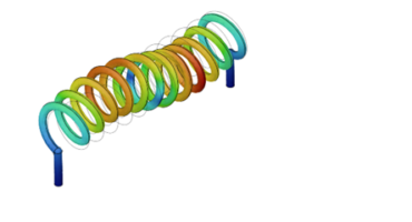 resonance causing catastrophic failure is arguably the well documented Tacoma Narrows Bridge collapse, where excessive oscillating deflections were introduced by 40-mile-per-hour winds exciting the suspended structure. When designing a vibration sensor, the effect of self-resonance may be considered less dramatic. However, it can mean that misleading peaks at certain frequencies in the measured vibration data plots, will be visible to the end user.
Ideally, if you can perform a frequency sweep, and then measure the frequency responses where high amplitude measurements occur, then it can be determined if there are any self-resonances within the actual measurement range of the sensor. Simulations can be carried out using modal frequency analysis software. This software is becoming more readily accessible and is provided by many of the main 3D CAD design packages as either a free or upgrade add-on. Be careful with simplifications that you make to your CAD geometry and the material properties provided or other inputs for the simulation, including dynamic parameters that may influence the results.
There are many 1.0 to 2.5kHz sensors on the market that may be manipulated to push those modal frequencies above the measurement range of the sensor. Just like mounting an engine on spring mounts with addition or reduction of mass, make sure you utilise techniques to change the frequency response of your system. Increasing stiffness, adding relieving cut-outs, changing the bracing/fastening, adding isolating features, encapsulation, understanding the individual and overall centre of gravities, changing or adding materials, etc, are just some of the things that you can try to learn more about the system responses.
The market now has more affordable 5.0 to 10.0kHz plus, sensors being developed. As a result, it might be almost impossible to try to shift all individual modal frequencies above the now wider measurement range, through design. With that in mind, the more important considerations will need to be more closely tied to the application, and less about eliminating them completely. Understanding the frequencies generated by the different types of equipment you are planning to monitor, will help you to decide which design manipulations you need to adopt to avoid self-induced noise.