Interference of electrical signals, whether through radio frequencies (RF), electromagnetic forces (EMI) or other sources, has long been recognized as an issue that can plague accelerometer applications. This electrical interference can manifest as increased noise, signal interruption, or erroneous data altogether, eroding trust in the measurement system and complicating machine fault analysis. While many applications will not encounter the types of signals that cause this noise, some will have handheld communication devices, high-frequency radios or other items that radiate noise in use nearby, and need to ensure their signals are unaffected. Properly grounding the sensor is important for minimizing RF and other types of interference and obtaining more reliable data.
The majority of vibration sensors are internally shielded, or case-isolated, to protect against the most common methods of such interference and pass further electrical tests to be deemed compliant with CE regulatory standards. That does not mean, however, that they are completely resistant to these outside forces and oftentimes results in the need for specific wiring configurations to avoid further interference.
Since accelerometers operate at maximum frequencies of about 10 kHz, steady sinusoidal radio frequency signals operating at greater than 500 kHz can be rejected using low-pass filters. However, in order to transmit information, these RF signals are often modulated at frequencies within the frequency band of the sensors. If these signals gain access to the cable or other parts of the wiring they will encounter the termination of the accelerometer’s circuit, manifesting themselves in the signal output. Even if the RF signal is not modulated, which is equivalent to modulation at a frequency of zero, the DC bias output voltage (BOV) of the two-wire sensor, a key troubleshooting tool, can shift. Once the signal has been detected by the sensor electronics, it can no longer be filtered without making the accelerometer inoperable.
The accelerometer circuit can be redesigned to reduce these effects, but that would result in other disadvantages such as increased noise. Alternately, the powering scheme could be modified to require a constant voltage as opposed to a constant current, but these changes would only be a temporary solution and not address the root cause of the issue. Therefore, it is essential that the wiring system be properly organized to prevent the RF signal from entering the cable, as effective shielding is the most important measure in curing and avoiding such interference.
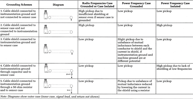
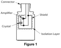 In order to obtain maximum effectiveness of a particular shielding measure, no breaks or points of entry should be permitted in the shield and both ends of the shield must be terminated properly. The methods outlined in the table below show different grounding schemes for various connections of the outer shield and how they affect RF and power frequencies. They apply to a sensor that is case-isolated, as mentioned previously and seen in Figure 1, with internal amplification and a relatively low output impedance. The outer case must be isolated from signal return to prevent ground loops at power frequencies and its connector is attached to the outer housing or case. The signal is to be transmitted using a twisted, shielded-pair cable, providing better shielding than a coaxial cable. In these scenarios, the sensor is also electrically isolated from the machine it is mounted to via an isolating epoxy or mounting pad, though that may not always be the case and should be verified for each application.
It should be noted that if the sensor housing is not connected to the shield, there exists a short, exposed lead acting as an antenna inside the connector and a short, exposed lead between the connector and the inner housing. Grounding just the housing to the structure itself does not provide any shielding from RF interference. The best solution for RF interference is to mount the accelerometer to an electrically isolated mounting pad and connect both ends of the shield directly. For battery-powered data collectors, the shield can also be tied to both ends directly without the use of a mounting pad.
A better design, though more difficult mechanically for case isolated accelerometers, would be to attach the connector to the inner housing or signal return, which is electrically isolated from the structure to which the accelerometer is attached. The shield can be connected to the instrumentation ground without creating large currents in the cable shield in case the machine and instrumentation are at different power frequency potentials. For base-isolated accelerometer designs where the shield is connected to the signal return, the connector is also attached to the signal return and therefore has no RF opening at the connector.
Following the recommendations given in the table above will provide the best possibilities for avoiding and eliminating RF interference, something even aluminum foil can’t always do!