The analysis of machine states in CBM can be accomplished using various methods. The most common methods are analysis in the time domain, analysis in the frequency domain, and a mix of the two.
- Time-Based Analysis
In vibration analysis in the time domain, the effective value (root mean square, or rms for short), the peak-to-peak value, and the amplitude of vibration are considered (see figure below).
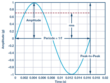
Amplitude, effective value, and peak-to-peak value of a harmonic vibration signal.
The peak-to-peak value reflects the maximum deflection of the motor shaft and thus allows conclusions about its maximum loading to be made. The amplitude value, in contrast, describes the magnitude of the occurring vibration and identifies unusual shock events. However, the duration or the energy during the vibration event and hence the destructive capability are not considered. The effective value is thus usually the most meaningful because it considers both the vibration time history and the vibration amplitude value. A correlation for the statistical threshold for the rms vibration can be obtained through the dependencies of all of these parameters on the motor speed.
This type of analysis proves to be very simple because it requires neither fundamental system knowledge nor any type of spectral analysis.
- Frequency-Based Analysis
With frequency-based analysis, the temporally changing vibration signal is decomposed into its frequency components via a fast Fourier transform (FFT). The resulting spectrum plot of magnitude vs. frequency enables monitoring of specific frequency components as well as their harmonics and sidebands, as shown in the figure below.
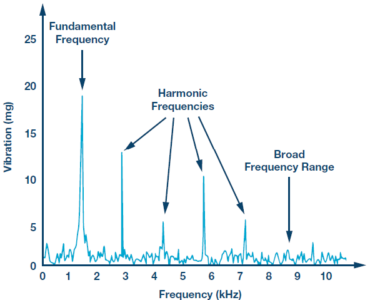
Spectrum plot of vibration vs. frequency.
The FFT is a widespread method used in vibration analysis, especially for detecting bearing damage. With it, a corresponding component can be assigned to each frequency component. Through the FFT, the dominant frequency of the repetitive pulses of certain faults caused by contact between rolling elements and defective regions can be filtered out. Due to their different frequency components, different types of bearing damage can be differentiated (damage on outer race, on inner race, or in ball bearing). However, precise information about the bearing, motor, and the complete system is needed for this.
Additionally, the FFT process requires that discrete time blocks of the vibration be repeatedly recorded and processed in a microcontroller. Although this requires slightly more computing power than time-based analysis does, it leads to more detailed analysis of the damage.
- Combination of Time- and Frequency-Based Analysis
This type of analysis is the most comprehensive because it combines the advantages of both methods. The statistical analysis in the time domain provides information about the vibration intensity of the system over time and at the same time whether or not it is within the permissible range. The frequency-based analysis enables monitoring of speed in the form of the fundamental frequency as well as further harmonic components required for precise identification of the fault symptoms.
The tracking of the fundamental frequency is especially decisive because the effective values and other statistical parameters change with speed. If the statistical parameters change significantly from the last measurement, the fundamental frequency must be checked so that possible false alarms can be avoided.
A change in the respectively measured values over time is common to all three analytical methods. A possible method for monitoring the system can involve first recording the healthy condition, or generating a so-called fingerprint. It is then compared with the constantly recorded data. In the case of excessive deviations or when exceeding the corresponding threshold values, a reaction is necessary. As shown in the figure below, possible reactions can be warnings (2) or alarms (4). Depending on the severity, the deviations may also require immediate intervention by service personnel.
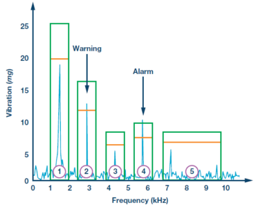
Threshold values and reactions for the FFT.
This tip adapted from the technology article found here.