Introduction
The standards working group behind the present edition of IEEE Std 43 made significant changes in the overall standard, including modifications to temperature normalization to 40°C. This was done to accommodate the many changes and observations in insulation chemistry and combinations over the past decades. There were some contentious issues, such as the continued inclusion of random wound machines for specific tests, since the makeup of the working group was focused around large, high voltage machinery with a relatively small contingent of representatives with integral horsepower, random wound machine experience. The result was a document written from the ground up and the inclusion of tests that have been in use for about a century, but not previously included in the standard.
The test outlined in Annex D represents the Insulation Resistance Profile (IRP), which is a method of interpreting the Polarization Index (PI) curve and related patterns and capacitive discharges. The original version of Annex D provided details, including interpretation of the data, which was generally agreed to by the participants with experience performing these tests. However, due to a lack of experience by a significant number of the group related to this test and deadlines for the standard, it was determined that a simple paragraph referencing the testing methodology would be in order.
What impact could Annex D have for a service company or consultant?
In one case, during a review of several medium voltage, form wound rewinds, a repair center converted their VPI tank to a new supplier. During quality assurance testing, the first rewind using the older system was evaluated and the IRP was a smooth curve. Following the replacement of the tank, the second rewind showed a different curve with significant discharges. It was initially assumed that the material had not properly cured. A second cure created a burned look to the insulation material. Further investigation identified that the new material supplier used glycol as a filler/thinner, reducing the tank’s voltage rating to well under a thousand volts per mil. All other tests performed, with the exception of the tank capacitance curve, showed passable results.
In other cases, the comparison of a good IRP to a post-repair can identify defects relatively quickly; and, in the case of field service, can be used to evaluate the condition of machines as part of a predictive maintenance program, or even one-time testing situations. While the IRP is one of many methods for evaluating an electric machine’s insulation system, we will focus on its uses within this article and how it is used to detect machine conditions.
The Concept Behind the IRP
While it may seem the IRP is something new, there are references that go back to the early 1900s in which operators of insulation testing meters were instructed to watch the needles on their meters for deflections. It has been understood that the materials within an electric machine make it a large capacitor, as the dielectric, referred to as an ‘insulation system,’ is between the conductive surfaces of the windings and the windings and stator core. The geometry of the system, layers of materials with different dielectric constants, variants in material thickness, the distance of conductors to ground across the dielectric, and other factors all affect the leakage, or insulation resistance, of a winding. The addition of foreign materials with dielectric constants, such as moisture, oils, grease, and other contaminants, cause a change in the capacitance where it comes between conductors and ground, as well as surface paths across the insulating material. Damaged insulation material also effects the overall system leakage, especially where tracking has occurred, resulting in carbonization of dielectric materials and a subsequent change in dielectric constant.
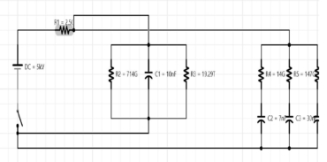
Figure 1: Insulation Resistance Model for a Machine
Figure 1 identifies: the series resistance of the test instrument (2.5 GigOhms); the surface leakage (714 GigOhms); geometric capacitance of 10 nF; conduction resistance of 19.29 TerraOhms; and absorption current and capacitance of 14 GigOhms, 147 GigOhms, 307 GigOhms and 7 nF.
As noted in IEEE Std 43, the measurement of insulation resistance is not particularly simple, as there are a variety of leakage currents across the dielectric material. The result is a series of charges that occur as a dielectric material polarizes, with the appearance of continual insulation resistance increase during the measurement process. The currents associated with insulation resistance include: conduction current (Ig), which is constant with time; absorption current (Ia), which is the current associated with polarization; surface leakage current (Il), which is constant over time and exists over the surface of the end turns to ground; and, geometric capacitive current (Ic), which relates to the internal resistance of the instrument and the geometry of the insulation system.
Each type of defect in the insulation to ground system of the electric machine, and other insulation systems, impacts one or more of these currents. These cause variations in the overall insulation curve, allowing the technician to determine different types of issues with a high degree of confidence.
Case 1: Contaminated New Motor Varnish
Taking a straight insulation resistance test will provide a value that can be corrected for temperature. In this example, a new motor has a high insulation resistance at 20°C (211 GigOhms), which is 52 GigOhms at 40°C, measured using an Amprobe AMB-55. Most people would be satisfied with this value in a random wound, 5 horsepower electric motor, as well as the raw Polarization Index (PI) of 4.59 and Dielectric Absorption (DA) of 2.86. However, when the complete picture is provided by looking at the insulation curve, a different view emerges.
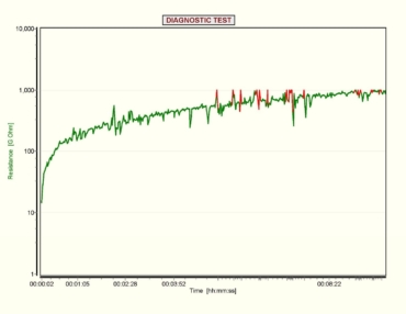
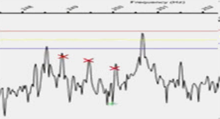
Figure 2: Insulation Resistance Profile of 5 HP Random Wound Motor
The impulses of discharged current cause a negative dip in the insulation resistance on the curve, which indicates defects in the capacitance of some portion of the insulation material. The increases in insulation resistance are related to points where the capacitance improves suddenly, also indicating issues with the insulation system. It is normal when the increases occur just before a discharge.
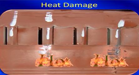
With the endshield removed, it became apparent that the varnish insulation had not been fully cured and that contaminants existed within the material. The result is a situation where the materials are less than what should be acceptable.
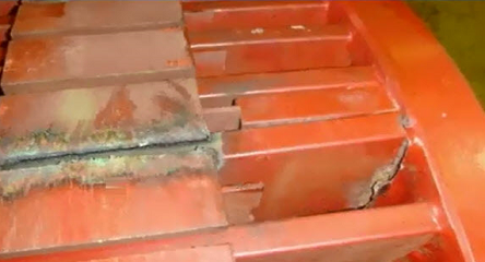
Case 2: Large Synchronous Motor Stator
A 4500 hp, 1800 RPM, 13.8kV synchronous motor had been operating under varying loads for approximately 15 years. During predictive maintenance testing the IRP was performed with an Amprobe AMB-55. The result, demonstrating low level discharge across the curve, is common for a contaminated insulation system. A visual inspection identified oil and moisture in the stator.
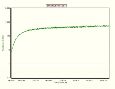
Figure 3: Contaminated Insulation IRP Pattern
The stator was cleaned, dipped, and baked prior to adding controls that would increase stress on the insulation system of the machine. The detection and correction of the contaminated winding improved the reliability of the motor.
Case 3: Stored Motor Issue
When the neutral of a motor can be split, an individual phase IRP can be performed with the other two phases grounded. This machine was evaluated using a Megger BM25 tester with data collected every 3 seconds and compared. While the frequency of collected data did not allow for the detection of sudden charges and discharges, it did clearly show that one phase was different than the other two, an indication that the leakage was high.
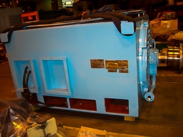
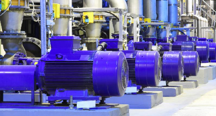
Figure 4: Motor Being Tested
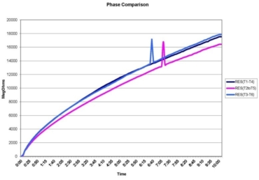
Figure 5: Insulation Resistance Profile of Individual Phases
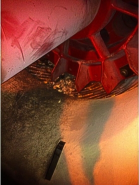
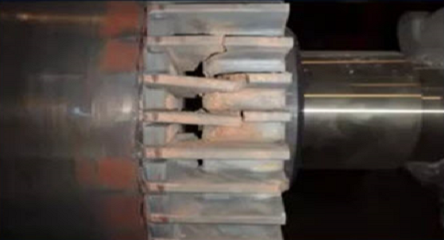
Figure 6: Rodent Nest Found in Motor
The motor had previously been overhauled and then placed in a storage location. When the inspection covers were removed after storage, it was discovered that rodents had nested in the bottom of the motor. Cleaning and repairing the insulation material where it had been gnawed brought the motor back to good operating condition.
Conclusion
There are multiple patterns with the IRP that can be used to detect issues from aged insulation systems to contamination. Having an understanding that performing a PI involves monitoring the insulation resistance results and watching closely for variations will allow the technician to detect problems early. This can be performed with advanced testing equipment or hand-held instruments where the insulation resistance is still in the measuring range of the instrument.
While the concept of the IRP has been in place for over a century, the method was finally introduced into the IEEE Std 43-2013 edition. The committee debated how much detail would be included, as only a few of the engineers involved had experience with fault detection using this method. The original three to five pages of fault patterns were removed and a paragraph describing the IRP was included as Annex D.