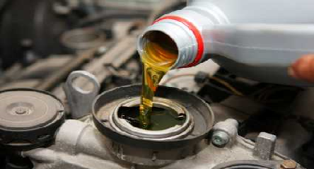
Through this article, I am going to answer a question received before regarding use of motor oil in a Heavy-duty reciprocating compressor.
Description of the question:
“Can automotive SAE 20W -50 motor oil be used in reciprocating compressors? Our double-acting heavy-duty piston compressor has an oil capacity of about 4000 liters and used to condense air for a process unit in a refinery located in central parts of Iran, in a mountainous area. We want to check if we can use SAE 20W-50 motor oil instead of Shell Corena S2 P100 compressor oil used since years ago at this compressor to reduce costs?”
The answer to this question consists of 4 parts: General knowledge of a reciprocating compressor’s structure, engine oil vs. compressor oil, effects of using engine oil in compressors, and finally, conclusion.
- General knowledge of a reciprocating compressor’s structure
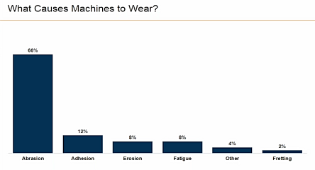
Generally speaking, compressors are divided into two categories: positive displacement and dynamic compressors. In the first type (which is under consider in this article), gas (in this case: air) is sucked into a completely closed and sealed chamber (e.g., a cylinder) and is compressed by a piston and exits to a sealed circuit. The working basis of dynamic compressors (which will not covered in this article) is entrenched under the fact that the velocity of the gas is increased by the movement of a series of vanes and then reduced to a great extent resulting in pressure increase.
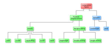
Figure 1: Compressor types (Source: Wikipedia)
As indicated in Fig.1, positive displacement compressors are divided into two groups: reciprocating and rotary compressors, which themselves are divided into three categories in the reciprocating sub-division: single-acting, double-acting, and diaphragm-controlled. Among these three categories, the single stage reciprocating compressors are compressors that expel the dense gas (in this case: air) once with each revolution of the crankshaft. These types of compressors have different configurations, an example of which is shown in Fig. 2.
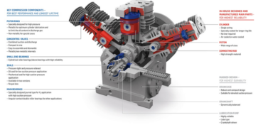
Figure 2: Holographic view of a single stage reciprocating compressor configuration (Source: Burckhardt Compression)
However, the compressor type covered in this paper is a two-stage compressor, meaning it can expel dense air from two outlets with each turn of the crank. Most heavy and large reciprocating compressors use this mechanism to compress air (or other types of gas as specified by the designer or customer order). This type of compressor, like the single-stage mode, can use various configurations, an example of which is shown in Fig. 3.
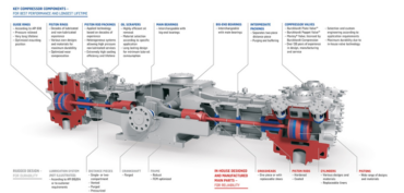
Figure 3: Holographic view of a two-stage reciprocating compressor configuration (Source: Burckhardt Compression)
Although various types of reciprocating compressors have been designed and manufactured, but the general operation mechanism is more or less the same in all of them. To compress the air, one (or more) pistons must move in one (or more) cylinders, and the dynamics of these pistons is controlled by a piston rod (or connecting rod), the other end of which is connected to the crankshaft.
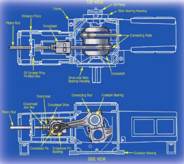
Figure 4: General view of how a piston connected to the crankshaft and its movement in the cylinder of reciprocating compressors [1]
The crankshaft can also be driven by an internal combustion engine or an electric motor, and its motion can be controlled by various mechanical tools such as flywheels and gears. To lubricate the movement and limit the dynamics of the piston and its accessories, a lubrication system is used. An example of its details can be found in Fig. 5.
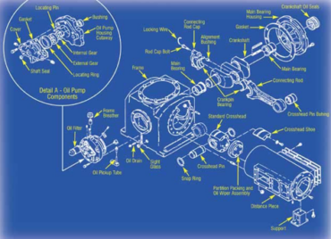
Figure 5: General view of various parts used to lubricate and limit the movement of the piston in reciprocating compressors [1]
When the piston rises, the air in the cylinder is compressed (see diagram in Fig. 6) and forced into the pneumatic circuit through the exhaust valve. While the piston lowers, a constant volume of fresh air is drawn into the cylinder. Each step of this process is controlled by internal and external valves.
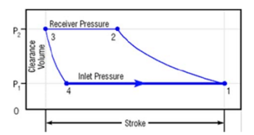
Figure 6: Thermodynamic diagram of a reciprocating compressor operation [1]
Cooling of such a compressor can be accomplished by two ways: either by air circulation around the piston rod or by the water jacket around the cylinder. Of course, there are many different designs in this regard, but the goal is the same for all of them.
So far, as we have seen, there are many similarities between reciprocating compressors and internal combustion engines. In both of these thermodynamic systems there are cylinders and pistons, and in both the crankshaft (and its control accessories) is used to limit the dynamics of the piston. However, reciprocating compressors have some differences in their structure from internal combustion engines:
1st– in reciprocating compressors, the cylinder head valves (which may be installed in a different part depending on the configuration desired by the designer or customer) operate automatically. On the other hand, in internal combustion engines, the operation of these valves is controlled by a mechanical unit (camshaft or something else) or an electronic unit (ECU, belt or timing chain, etc.);
2nd– in reciprocating compressors (usually two-stage, where the oil chamber is pressurized), the piston crank is not directly connected to the crankshaft, but an intermediate piece is used, called a crosshead (Fig. 3 and 4), which has its own advantages. Among other things, by using this device, you can use a different oil in the cylinder part or not lubricate it at all!
3rd– from lubrication point of view, the piston of a compressor may not be exposed to the temperature orders of several thousand degrees Celsius during the combustion of the fuel-air mixture inside the cylinder. Therefore, the material of the piston crown and its rings might be completely different from that used in internal combustion engines. According to the author’s personal experience, this difference may concern the material quality, the type of coating or even the metallurgical structure and the manufacturing process. Since the engine oil system is designed for taking temperatures up to 120°C, the additives used in its chemical structure can be completely different from the oils used in reciprocating compressors and despite the fact that compressor oils are not even supposed to reach a temperature of 100 degrees Celsius, however, supposed to show their performance primarily at temperatures of 0 to 60°C.
4th– from the oil analysis point of view, in the elemental analysis tests of compressor oils, the maximum and minimum limits for elements such as iron (Fe), chromium (Cr), aluminum (Al), copper (Cu), and especially silicon (Si) are completely different from those of engine oils, this extreme difference is due to the nature of the additives used in the chemical structure of this type of oils compared to engine oils. We will talk more about this issue in the next section.
- Engine oil vs. compressor oil
Before start, it’ll be better to know a little about the functions of oil in an internal combustion engine versus reciprocating compressor. As the most widely used in industry, air compressor put severe oxidation stress on the oil due to the presence of hot air under high pressure, catalytically active metal salts and oxides, e.g., Fe2O3, and condensed water, generated by compression. Whereas, Lubricants for internal combustion engines are exposed to severe oxidative conditions, particularly in the upper part of the piston ring and the cylinder liner zone where maximum temperatures can exceed 250°C in a passenger car engine and 300°C in a heavy-duty diesel. In these areas, thin oil films, ∼5×10⁻⁷ m, are exposed to blow-by gases during a residence time of 2–5 min. High temperatures and the reactive blow-by gases lead to rapid oxidation of the thin oil film, which is initiated by hydroxyl and NO2 radicals. The nitrogen oxides also react with fuel-derived olefins in the blow-by, leading to sludge precursor. Because the piston area and the crankcase are exposed to the same lubricant, all degradation intermediates such as free radicals, nitro (RNO2) and nitroso compounds (RNO), nitrites (RONO), nitrates (RONO2), acids, ketones and oil-soluble polycondensation and polymerization products are transferred to the sump. In addition, the blow-by gas carrying sludge precursors condenses in the crankcase oil. With extended oil change intervals and crankcase oil temperatures up to 160°C, oil thickening, sludge and deposit formation are very common in motor oils [11]. The main function of motor oils compared to compressor oils in the absence of thermal shock is summarized in table 1:
Table 1: Summarized comparison of engine oils and reciprocating compressor oils [2,5,7]
| IC Engine Oils |
Reciprocating Compressors |
| 1) Helping to seal the piston & cylinder
2) Burning off the cylinder wall without leaving any residue
3) Heat dissipation from liners, piston, & rings
4) Neutralization and hold in suspension the by-products produced due to blow-by gases formed when fuel is burned
5) Transportation of soot and sludge particles caused by incomplete combustion
6) Emulsification of any water formed during the combustion process
7) Protection of parts from corrosion; and
8) Reduce friction and wear during extreme, low temperature
start-ups as well as when the lubricating film is subject to high temperatures and pressures in bearings and around the piston rings. |
1) Separation of frictional parts from each other.
2) Dissipation of heat caused by friction through cooling and heat transfer.
3) Removal of dirt and other solid impurities entering the system.
4) Minimizing erosion.
5) Reduction of friction losses.
6) Reduction of gas leakage (in this case: air).
7) Protection of parts from corrosion; and
8) Reducing the deposition of contaminants in the oil stream
|
| Critical Parts to be Lubricated |
| Turbocharger:
– Operating at high-speeds up to 250,000rpm
– Peak temperature of 1000°C |
Cylinder liners, Pistons, & Rings:
– Sensitive to wear and deposit formation in the lubricant |
| Cylinder liners, Pistons, & Rings:
– Sensitive to control deposit formation in the lubricant
– Deposits cause piston-ring sticking |
Compressor frame:
– Compressor key moving parts protection, e.g., crosshead, connecting rods, & crankshaft
– Motorshaft and crankshaft are one-piece, eliminating the need for a coupling |
| Crankcase:
– Engine key parts protection, e.g., crankshaft, connecting rods, capillary oil feeds
– Sensitive to capillary oil feeds clog due to soot, sludge, & debris |
Valves:
– Sensitive to corrosion due to moisture and liquid phase process fluid |
| Valve train:
– Controlling the amount of air and exhaust gas flowing into and out of the engine
– Exact geometry of the cam operated mechanism is crucial and sensitive to soot and wear formation |
Main and rod bearings:
– Supporting the crankshaft and connecting rods, providing crankshaft and crank pin rotation through plain bearings at several journals
– Sensitive to corrosion and lack of lubrication |
| Main and rod bearings:
– Supporting the crankshaft and connecting rods, providing crankshaft and crank pin rotation
– Sensitive to corrosion and lack of lubrication |
|
As it can be seen from table 1, the main difference between two identical in viscosity grade engine oil and reciprocating compressor oil is summarized in viscosity index which for Shell Corena S2 P100 is calculated as VI=51 and for Behran BGT SAE 20W-50 (API SE) as one of the cheapest motor oils in Iran is indicated as VI=120 [8]. This big difference is not surprising cause the Shell compressor oil doesn’t need a high viscosity index, due to lack of thermal shock as big as existed in an internal combustion engine. Taking a glance at table 2 will be more clarifying the case.
Table 2: Summarized comparison of additives used in motor and compressor oils [5,9,10,11,12]
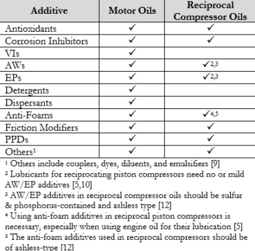
From table 2, it can be seen that reciprocal compressor oils don’t need viscosity improvers in their chemical composition due to lack of sever thermal shock in their working environment. In this way, we should first investigate the mechanical behavior of two oils SAE 20W-50 and Shell Corena S2 P100 against heat numerically and mathematically. Look at the diagram depicted in Fig. 7. This diagram shows the non-linear behavior of the kinematic viscosity of SAE 20W-50 engine oil against the heat.
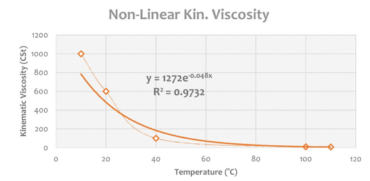
Figure 7: Non-linear diagram of kinematic viscosity of SAE 20W -50 oil against heat (curve fitting error: 2.68%)
As expected, the nonlinear behavior of the SAE 20W-50 kinematic viscosity as a function of heat follows an exponential trend. The graph in Fig. 8 shows the linear behavior of the same oil with regard to 40 and 100°C as check points.
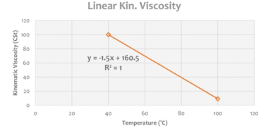
Figure 8: Linear plot of kinematic viscosity of SAE 20W -50 oil against heat (fitting error: zero)
In other side, Shell Corena S2 P100 compressor oil behavior against temperature rise indicated in Fig. 9 and 10 for non-linear and linear behavior, respectively.
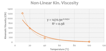
Figure 9: Non-linear diagram of the kinematic viscosity of Shell Corena S2 P100 compressor oil as a function of heat (curve fitting error: 2.00%)
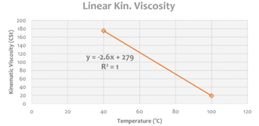
Figure 10: Linear plot of the kinematic viscosity for Shell Corena oil S2 P100 as a function of heat (fitting error: zero)
From the diagrams in Fig. 7 and 9, it can be concluded that in the temperature range of 20 to 60°C, Shell Corena S2 P100 compressor oil loses its viscosity by about 16% faster than SAE 20W-50 engine oil which means that compressor oil flows faster in the lubrication circuit in the mentioned temperature range. However, looking at the graphs in Fig. 8 and 10, it can be concluded that although Shell compressor oil has a higher initial viscosity than engine oil, it decreases by about 73% when heated. This difference is even more evident in Figure 12.
So, the first result we can draw from the numerical analysis of diagrams 7 to 10 is that Shell Corena S2 P100 compressor oil moves faster in the oil supply circuit and exerts less pressure on the oil pump in the normal operating temperature range of the compressor. This means a thinner oil film layer in this temperature range for the parts of the compressor (especially in the cylinder area), but this is compensated for by the faster oil flow in the circuit.
The diagrams shown in Fig. 11 and 12 are the result of combining diagrams 7 to 10.
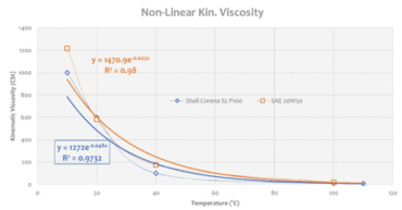
Figure 11: Cumulative diagram of the nonlinear behavior for kinematic viscosity of two oils SAE 20W-50 and Shell Corena S2 P100 versus temperature
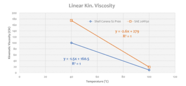
Figure 12: Cumulative diagram of the linear behavior for kinematic viscosity of SAE 20W -50 and Shell Corena S2 P100 oils versus temperature
- The effects of using engine oil in a compressor
Before we begin the discussion on this topic, we shall review two sources on the use of engine oil in compressors:
– On one hand, motor oils can be used in portable and small reciprocating air compressors which contain detergent-dispersant additives. It is also recommended to use motor oils instead of turbine oils, etc. in fixed piston compressors where the moisture content of the air under their production pressure is high [3].
– On the other hand, detergent-dispersant motor oils are recommended for lubricating small air piston compressors. This is because this type of oil has very good oxidation resistance [4].
Based on these two reliable sources, one can easily use SAE 20W-50 engine oil and save big on his/her purchase! But there are two things to keep in mind:
– The compressor is not small! and more importantly
– The humidity in the area is not high!
So, it is completely wrong to rely on the two sources mentioned above!
There is a remaining point from table 2, which addresses the fact that reciprocal compressor oils don’t need detergents and dispersants, in short: DD-additives, in their chemical structure. The DD-additives are a kind of multi-purpose lubricant additives mostly used in the structure of engine oils and some gear oils. The chemical structure of these additives is micelle-type due to their polarity requirement which consists of salt compounds of metals or semi-metals such as calcium, magnesium, sodium and barium. The order mentioned is based on the amount of consumption and frequency of use of these metals or quasi-metals in chemical compounds [5]. See Figure 13.
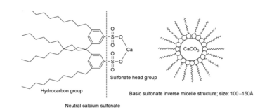
Figure 13: Micelle-like structure of detergent additives [6]
The main functions of DD-additives are divided in two categories: in detergent mode, micelle compounds adhere to acidic particles and detach them from metallic surfaces. Hereafter, the dispersant mode is activated and prevents the particles from dispersing and spreading in the oil stream.
One of the best known of these chemical compounds are sulfonates, which are abundantly present in engine oils in the form of calcium sulfonate, sodium sulfonate or barium sulfonate. These additives are considered basic (alkaline) by their chemical structure and their purpose is to increase the total basicity number (TBN) of the oil system to prevent the formation of acidic compounds caused by presence of sulfur in combustion fuels (gasoline, diesel, etc.). However, for reciprocating compressors, high temperatures (leading to thermal shock), severe wear, fuel sulfur and… are out of order! For this reason, the TBN number of the oil system (when using engine oil instead of compressor oil) increases for no reason, and this high TBN has the following effects:
– formation of a layer of ash rich in calcium salts
– loss of oil system chemical stability
– Increased oil consumption
The formation (or rather, deposition) of a layer rich in calcium salts (which, of course, may also contain barium, sodium or magnesium salts) leads to the gradual crystallization of these salts and, due to the relatively high hardness of these crystals, to wear on certain compressor parts such as seat rings and seat valves. Over time, this corrosion and wear of surfaces can lead to leakage and oil loss (especially in drip lubrication systems), causing an increase in oil consumption. On the other hand, if TBN increases inappropriately, the oil system environment becomes over-basic which eventually leads to a decrease in oxidation resistance of the oil system (especially in mountainous environments where humidity is low or the temperature in the compressor working environment is low). Elevated oxidation risk, together with the presence of strong alkaline compounds, can eventually lead to the formation of compounds such as NaOH, especially in the cylinder and piston parts, which cause pitting corrosion on the piston front surface. Therefore, most manufacturers of heavy-duty reciprocating air compressors recommend the use of detergent-free oils to lubricate such compressors. This means that, based on the above two sources, equivalent engine oils that do not contain detergent-dispersant additives can be used if principles such as kinematic viscosity and density are satisfied.
In the lubrication of double-acting compressor cylinders, one of the most important factors is the rate of oil feed [18]. The lubrication system for compressor cylinders must be able to deliver relatively small amounts of oil (meaning drops or pints or quarts) at high pressure to reliably lubricate the wearing surfaces of the cylinders & piston rods. This is truly named as “lifeblood” for wearing components of the reciprocating compressors which include:
– Qualified lubricant selection for certain service conditions
– Cleanness during storage and dispensing
– Correct quantity application in a manner that permits effective performance [16]
To calculate the required lubricant feed rate for a specific compressor, there are two ways are available:
- A) Using oil feed rate diagram as a graphical means (shown in Figure 14) which is based on steps below:
- The compressor cylinder diameter or cylinder bore (in or mm), B which must be determined for each cylinder and is not constant in all cylinders.
- Piston stroke, S (in or mm) which assumed here as a constant.
After multiplying B by S, we must go for the next step:
- Compressor speed, N (rpm) as a constant measure.
- Discharge pressure, P (psig) as assumed constant.
After compiling these data together, the oil feed rate for each cylinder as pints per day will be resulted.
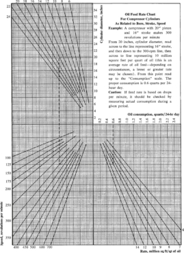
Figure 14: Oil feed rate chart for double-acting compressor cylinders [2,18]
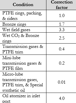
However, the resulting oil feed rate should be multiplied by the correction factor as indicated in table 3:
Table 3: Correction factor multiplied by oil feed rate for compressor cylinders having these conditions [13,14]
- B) Oil feed rate calculation:
The amount of oil fed to the compressor cylinders should be sufficient enough to provide lubrication and effectively seal the piston against leakage. Oil feeds above this certain rate are wasteful, causing oxidation or carbonizing the valves [19] and tend to overflooding oil carry-over to the distribution lines [2]. So, it is better to under-lubricate than over-lubricate [19] (see Figure 15).
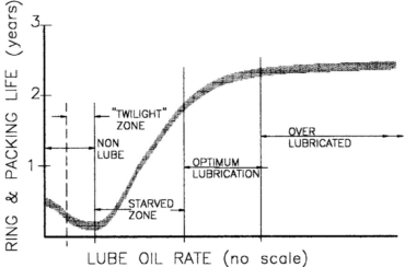
Figure 15: Compressor seal life vs. oil usage in different lubrication phases [13,14]
As it is shown in Figure 15, over-lubrication has no positive effect on ring and packing life and best results will be obtained when cylinders are lubricated in an optimum, precise, way. In this way, in a paper presented at the 2018 Gas Machinery Conference, C.J. Sloan claims an over-90% reduction in compressor lubricant consumption using a formula in order to calculate how much oil exactly every cylinder need per day (24 hours) [17]:
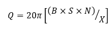
In the above-mentioned formula:
– Q: oil quantity needed to charge for every cylinder per 24 hours, in pints (approx. 473.18cc) or quarts (approx. 946.35cc)
– B: cylinder bore (in or mm)
In the above-mentioned formula:
– Q: oil quantity needed to charge for every cylinder per 24 hours, in pints (approx. 473.18cc) or quarts (approx. 946.35cc)
– B: cylinder bore (in or mm)
– S: piston stroke (in or mm)
– N: compressor running speed (rpm)
– X: swept surface area (ft2 or m2)
Which exact amount shall be determined as a function of oil kinematic viscosity (ν), which reflects the oil type (density) and its dynamic viscosity (η), cylinder discharge pressure (Pd) and temperature (Td), and gas composition (ρ).
For example, in case of clean methane and low-pressure plant air or dry gases [15] and using standard motor/compressor crankcase oil, the X=2,000,000ft2 [17]. However, some resources tried to simplify the X selection through choosing a general amount for X which covers all cases. For instance, X=5,000,000ft2 [18] or X=193,424,000ft2 [16]. Among all, I believe an average amount for X-factor may not lead to a precise estimation for every compressor and this case shall be solved using machine learning (ML) techniques.
- Conclusion
In accordance with the points made in sections 1, 2, and 3, the use of SAE 20W-50 oil for use in a heavy-duty compressor which operates in a mountainous area is not recommended.
- References
[1] Noria Corporation, Reciprocating Compressor Basics, Web article available at https://www.machinerylubrication.com/Read/775/reciprocating-compressor, accessed October 18th, 2017;
[2] H. P. Bloch & J. J. Hoefner, Reciprocating Compressors: Operation & Maintenance, Gulf Publishing Company (an imprint of Butterworth-Hememann), ISBN 0-88415-525-0, 1996, p108, pp117-120;
[3] D. M. Pirro, M. Webster, & E. Daschner, Lubrication Fundamentals, 3rd ed., CRC Press, ISBN 9781315367033, 2016, p415
[4] W. L. Robertson, Lubrication in Practice, 2nd ed., CRC Press, 1984, ISBN 9780203748589, p112
[5] T. Mang & W. Dresel (editors), Lubricants & Lubrication, 2nd edition, Wiley Publications, ISBN 978-3-527-61033-4, 2007, pp. 88-118
[6] L. R. Rudnick (editor), Lubricant Additives: Chemistry, & Applications, 3rd ed., CRC Press, ISBN 9781315120621, 2009, p134
[7] D. De Mesmaeker, Critical Engine Parts for Lubrication, Q8Oils, June 20th 2018, Web article available at https://www.q8oils.com/automotive/critical-engine-parts-lubrication/, accessed April 12th 2023
[8] Behran Oil Co., Behran BGT motor oil specifications, https://www.behranoil.co/en/product/2534-BGT.html, accessed at April 12th 2023
[9] G. E. Totten (Editor), S. R. Westbrook, and R. J. Shah (Section Editors), Fuels and Lubricants Handbook: Technology, Properties, Performance, and Testing, ASTM Manual Series: MNL37WCD, ISBN 0-8031-2096-6, 2003, pp199-242
[10] W. Bock, G.Lingg, Ullmann’s Encyclopedia of Industrial Chemistry, Lubricants, 6. Compressor & Turbine Oils, Vol. 21, Wiley-VCH, DOI: 10.1002/14356007.o15_o08, 2012, pp497-517
[11] R. M. Mortier, M. F. Fox, S. T. Orszulik (Editors), Chemistry and Technology of Lubricants, 3rd ed., Springer, ISBN 978-1-4020-8662-5, DOI 10.1023/b105569, 2010, pp137-140
[12] Patent No. WO 2015/052558 Al, Compressor Oil & Compressor Oil Additive Composition, International Application Number PCT/IB2013/061018, International Publication Date Apr.,6th, 2015, available at https://patents.google.com/patent/WO2015052558A1/en
[13] J. Jamison Schulthess, Reciprocating Compressor Lubrication – Lubricant Dilution with Natural Gas Species & the Impact on Lubrication Rates at Various Operating Condistions, Thesis in partial fulfillment of the requirements for the degree of Master of Science, Colorado State University, 2021, pp13-25
[14] P. C. Hanlon (Editor), Compressor Handbook, McGraw-Hill, ISBN 0-07-026005-2, 2001, pp18.7-18.10
[15] R. Scott, Reciprocating Natural Gas Compressors, Machinery Lubrication (11/2003), Web Article available at https://www.machinerylubrication.com/Read/552/reciprocating-natural-gas-compressors, Accessed April 14, 2023
[16] M. Samancioglu, Compressor Cylinder & Packing Lubrication, Web article available at htps://www.linkedin.com/pulse/compressor-cylinder-packing-lubrication-mehmet-samancioglu/, Accessed April 14, 2023
[17] C.J. Sloan, Innovations in Compressor Cylinder & Rod Packing Lubrication: Approaches & Results, Gas Compression Magazine, Nov. 2018, http://www.gascompressionmagazine.com
[18] H. P. Bloch, Practical Lubrication for Industrial Facilities, 2nd ed., CRC Press, ISBN 0-88173-580-9, 2009, pp323-325
[19] EP Editorial Staff, Compressor Lubrication, Part IV-A: Positive-Displacement Types, August 8, 2012, Web article available at htps://www.efficientplantmag.com/2012/08/compressor-lubrication-part-iv-a-positive-displacement-types/, Accessed April 14, 2023