How To Check Your Windings on Three Phase Motors
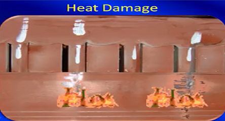
Motor windings are conductive wires wrapped around a magnetic core; they provide a path for current to flow to create then magnetic field to spin the rotor. Like any other part of the motor, the winding can fail. When motor windings fail it’s very seldom that the actual conductors fail, rather it is the polymer coating (insulation) surrounding the conductors that fail. The polymer material is organic in its chemical composition and is subject to change due to aging, carbonization, heat, or other adverse conditions that cause a chemical composition of polymer material to change. These changes cannot be detected visually, or even with traditional electrical testing instruments like ohmmeters or megohmmeters.
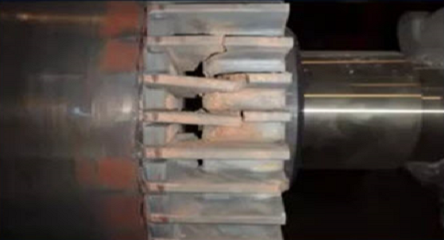
The sudden failure of any part of the motor will cause loss of production, increased maintenance expense, loss, or damage to capital and possibly personal injury. Since most insulation failure occurs over time, MCA technology provides the measurements required to identify these small changes that determine the condition of the winding insulation system. Knowing how to check your windings will allow your team to be proactive and take the appropriate action to prevent unwanted motor failure.
How to Test Groundwall Insulation
A ground fault or a short to ground occurs when the resistance value of the ground wall insulation decreases and allows the current to flow to ground or an exposed part of the machine. This creates a safety issue since it provides a path for the supply voltage from the winding to extend to the frame or other exposed parts of the machine. To test the condition of the ground wall insulation measurements are made from the winding leads T1, T2, T3 to ground.
Best practices test the winding path to ground. This test provides a DC voltage to the motor winding and measures how much current flows through the insulation to ground:
1) Test the motor deenergized by using a properly working voltmeter.
2) Place both instrument test leads to ground and verify a solid connection to ground of the instrument lead. Measure the insulation resistance to ground (IRG). This value should be 0 MΩ. If any value other than 0 displays, reconnect the test leads to ground and retest until a 0 reading is obtained.
3) Remove one of the test leads from ground and connect to each of the motor leads. Then measure the insulation resistance value of each lead to ground and verify the value exceeds the recommended minimum value for the motors supply voltage.
NEMA, IEC, IEEE, NFPA provide various tables and guidelines for the recommended test voltage and minimum insulation to ground values dependent on the motors supply voltage. This test identifies any weaknesses in the groundwall insulation system. The dissipation factor and capacitance to ground test provide additional indication of the overall condition of the insulation. The testing procedure for these tests are the same, but instead of applying a DC voltage, an AC signal is applied to provide better indication of the overall condition of the groundwall insulation.
How to Test Your Windings for Connection Issues, Open or Shorts
Connection issues: Connection issues create current unbalances between the phases in a three-phase motor, which causes excess heating and premature insulation failure.
Opens: Opens occur when a conductor or conductors break or separate. This may prevent the motor from starting or cause it to run in a “single-phase” condition, which draws excess current, overheating of the motor and premature failure.
Shorts: Shorts occur when the insulation surrounding the winding conductors breaks down between conductors. This allows the current to flow between conductors (short) instead of through the conductors. This creates heating at the fault leading to further degradation of the insulation between conductors and ultimately leads to failure.
Testing for winding faults requires performing a series of AC & DC measurements made between the motor leads and the measured values are compared, if the measurements are balanced winding are OK if they are unbalanced faults are indicated.
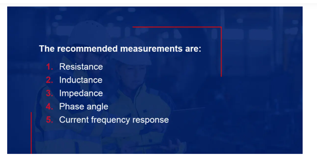
The recommended measurements are:
1) Resistance
2) Inductance
3) Impedance
4) Phase Angle
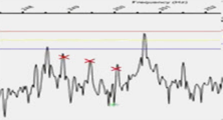
5) Current Frequency Response
Test your winding condition by testing these connections:
- T1 to T3
- T2 to T3
- T1 to T2
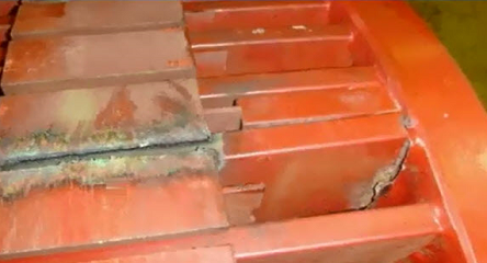
The reading should be between 0.3 to 2 ohms. If it is 0, there is a short. If it is over 2 ohms or infinite, there is an open. You can also dry the connector and retest to possibly get more accurate results. Check the inserts for burn marks and cables for wear.
Resistance unbalance indicates connection issues, if these values are out of balance by more than 5% from average, this indicates loose, high resistance connection, corrosion, or other build up on the motor terminals. Clean the motor leads and retest.
Opens are indicated by infinite resistance or impedance reading.
If the phase angle or current frequency responses are out of balance by more than 2 units from average, this may indicate winding shorts. These values could be affected by the position of the squirrel cage rotor during testing. If the impedance and inductance are out of balance by more than 3% from average, it is recommended to rotate the shaft approximately 30 degrees and retest. If the unbalance follows the rotor position, the unbalance could be the result of the rotor position. If the unbalance remains the same a stator fault is indicated.
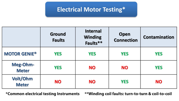
Traditional Motor Testing Instruments Are Not Able to Test or Check Motor Windings Effectively
The traditional instruments used for testing motors have been the megohmmeter, the ohm meter, or sometimes a multimeter. This is because of the availability of these instruments in most plants. The megohmmeter is used for safety testing of electrical equipment or systems and the multi-meter is used to perform most other electrical measurements. However, neither of these instruments by themselves or combined provides the information necessary to properly evaluate the condition of a motor’s insulation system. The megohmmeter can identify weaknesses in the motor’s groundwall insulation but does not provide the overall condition of the insulation system. It also does not provide information about the condition of the winding insulation system. The multi-meter will identify connection issues and opens in the motor windings but provides no information about the insulation between the windings.
Test Windings with Motor Circuit Analysis Testing (MCA™)
Motor Circuit Analysis Testing (MCA™) is a deenergized method that will thoroughly assess your motor health by checking windings and other parts. It is easy to use and quickly delivers accurate results. The ALL-TEST PRO 7™, ALL-TEST PRO 34™ and other MCA™ products can be used on any motor to identify potential issues and avoid costly repairs. MCA fully exercises the motors winding insulation system and identifies early degradation of the winding insulation system, as well as faults within the motor that lead to failure. MCA also diagnoses loose and faulty connections when the tests are performed from the motor.


Very nice summary. Concise and easy to follow.