Evaluation of Wound Rotor Motor with Electrical Signature Analysis
Howard W Penrose, Ph.D., CMRP
President, MotorDoc® LLC
The primary difference between an induction motor and a wound rotor motor is that the rotor has windings, slip rings and a variable resistance in order to vary speed or soft start an application. Can we detect issues in a wound rotor motor using voltage and current data through Electrical Signature Analysis (ESA)? In this article, we will identify a few additional defects that can be detected in a wound rotor motor on a crane.
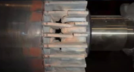
The crane motor is a 200 horsepower, 1200 RPM, 460 Vac, 60 Hz, 245 Amp motor with 54 rotor slots and 72 stator slots. The rotor slots would provide the same rotor and air gap-based calculations as a rotor with 54 rotor bars. There are also three slip rings, brush rigging and brushes. The failure history of this machine includes one of the slip rings failing. The motor is one of a pair that drives a gearbox and is reversible for raising and lowering loads.
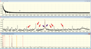
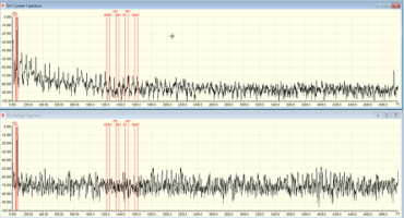
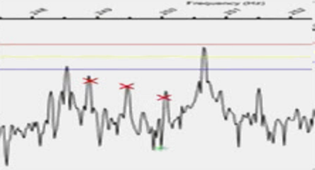
Figure 1 identifies pole pass frequency small peaks and Figure 2 identifies dynamic eccentricity using the EMPATH data collector and software. At this point, we must begin to apply some logic. Without rotor bars, what would cause a slight unbalance in the magnetic field in relation to the rotor slots? Shorted turns or a high resistance, most likely. This would be supported by a dynamic eccentricity, which would not be the result of a mechanical orbit in the air gap, but a magnetic orbit within the air gap due to an unbalanced rotor circuit.
While Figure 1 also shows gearbox conditions, the focus of this article is the failing rotor rings. With several motors having failed in the same way, we can assume that we probably have a high resistant connection. With an ALL-TEST PRO 5 motor circuit analyzer, we tested the rotor and stator separately by lifting the brushes and performing a stator test and then tested the rotor through the slip rings. Both the rotor and stator tested balanced, eliminating an internal open or short in the rotor. The recommendation was to evaluate the connections related to the resistor bank.
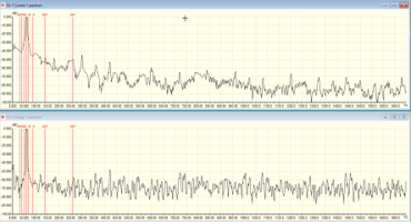
Loose connections were found in the rotor circuit and corrected. Follow-up data confirmed that the rotor problem was eliminated. The use of Electrical Signature Analysis is capable of identifying conditions such as rotor faults, connection and slip ring faults, resistor bank issues and related conditions.
Howard is the President of MotorDoc® LLC and the 2018 Chair of SMRP. He has over 35 years of electric motor testing, repair and design experience, starting with a US Navy motor repair job to advanced electric machinery design. Howard is also involved in legislation with the US Government regarding Cyber Security, Infrastructure, Energy, SmartGrid Education and Safety.
By using this site you agree to our use of cookies. You are free to manage this via your browser setting at any time. To learn more about how we use the cookies please see our cookies policy.