Electrical Insulation Failure
Electrical Insulation is used to direct current through a desired path and prevent it from flowing where it is not desired. Proper electrical insulation is critical to an electric motor’s performance and longevity. Insulation breakdown is one of the most frequent causes of electric motor failure. In electric generators, for instance, 56% of failures originate from electrical insulation damage.
Insulation Systems
In motors there are 2 insulation systems. One system is the groundwall insulation which separates the coils from the frame or casing of the motor. The second insulation system is the winding insulation system that separates the conductors that are coiled to create the motor windings. Studies have shown that ≈ 80% of stator electrical faults occur in the winding insulation while only ≈ 20% occur between the coils and the motor frame or direct short to ground.
What is insulation failure?
Electrical insulation failure occurs when the insulation in the motor begins to degrade over time or for other reasons. Aging or overheating causes chemical changes in the insulation that cause the insulation to become more conductive and become less effective at preventing the current from following undesirable paths either between the conductors or to the motor’s frame. Some insulation failures particularly in the ground wall insulation system are instantaneous due to moisture ingression, contamination, or other unusual unique events. These events attack voids or other weaknesses in the insulation and lead to premature failure. Faults in the winding insulation system materialize slowly and deteriorate over time.
Common causes of insulation failure include:
- Overheating
- Winding contamination
- Excessive current draw
- Poor power quality
- Harmonic distortion.
This guide will direct you through each stage of electrical insulation deterioration so you can be proactive and track these insulation changes in your motor equipment.
3 Stages of Electrical Insulation Failure
Most insulation failure occurs slowly and steadily, proceeding through three distinct stages.
Stage 1 — Ideal for Early Detection
During the first stage of the failure of electrical insulation, the insulation between conductors becomes stressed and begins to change chemically. The insulation chemically changes from an insulator and begins to become a conductor. The insulation strength and capacitance begin to decrease. The insulation may begin to carbonize which causes the current to become more resistive, and less capacitive. If the groundwall insulation undergoes the change this will cause the insulation resistance to decrease and the dissipation factor to increase. If the winding insulation undergoes the chemical change the phase angle (Fi) and/or the current frequency response will change.
Identifying faults at this stage of insulation failure is extremely important for reliable “world-class” operation of a plant’s electrical system. In this stage, undesirable current flow between conductors does not yet occur, though the risk that it will begin to do so is high. Fortunately, early detection through checking windings and engaging in proper motor testing is extremely beneficial. Early detection of insulation failure in electric motors allows a company to address the deterioration while it remains relatively minor, saving time and money and preventing catastrophic failure.
ALL-TEST Pro instruments are the only instruments in the world that can perform early detection of insulation failure in electric motors consistently and at the earliest stages.
See phase angle explained in detecting insulation failures below.
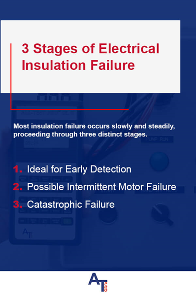
Stage 2 — Possible Intermittent Motor Failure
During the second stage of electrical insulation failure, the deterioration of the windings becomes more pronounced. Below are some of the failure characteristics they may exhibit:
- The degradation of the insulation material increases.
- The current continues to become more resistive.
- Heat increases at the primary point of insulation failure.
- The motor begins intermittently tripping the drive or circuit breaker, though it may continue to run once the insulation is cool.
Troubleshooting needs to be performed to determine the cause of the problem. ALL-TEST Pro instruments determine the true state of health on the motor and its components.
See phase angle, TVS™ & Current Frequency response explained in detecting insulation failures below.
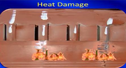
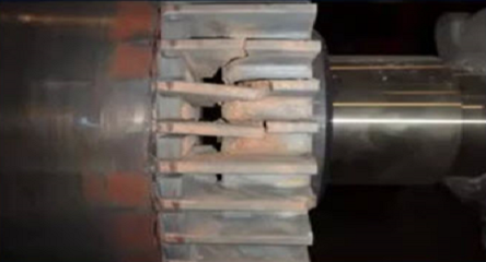
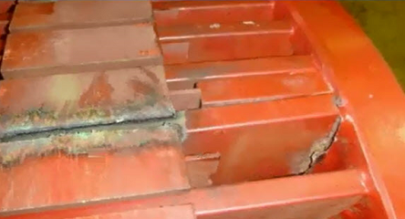
Stage 3 — Catastrophic Failure
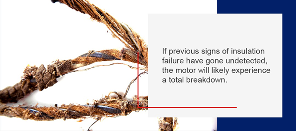
If previous signs of insulation failure have gone undetected or unaddressed, the motor will likely experience a total breakdown. Below are some of the characteristics the winding often exhibits at this stage:
- The insulation completely breaks down, creating a shortcut between winding or a direct path for the current from the winding to ground or motor frame.
- An explosive rupture develops at the fault point.
- Inductance and resistance changes occur.
- Copper coils begin to melt in response to excessive heat.
- The motor continually trips the drive or circuit breaker upon start up.
- The current flow between conductors is present.
Many electrical meters and devices should catch faults at this stage of motor failure (or when there is a complete short to ground indicating a severe safety issue). If you run motors to failure, then you may not need to know what is happening to your motor or know your motor’s state of health.
Causes of Insulation Failure
Stressors like temperature, pollutants, and electrical stresses such as sustained overvoltage’s can easily tax electrical insulation and cause breakdowns. The risk of insulation failure also increases with time as these various factors interact with each other to cause deterioration. For instance, tiny pinholes or cracks might appear in the insulation from everyday wear and tear. Those cracks weaken the insulation, and they also create avenues for moisture and chemical contaminants to enter, degrading the insulation even further.
Below are a few of the most common causes of electrical insulation failure in a motor:
- Contaminants: The winding insulation weakens because of contact with contaminants like machine tool coolant, oil and other chemicals. These contaminants often have a corrosive effect, breaking down the insulation over time. Moist contaminants are usually conductive because they contain impurities, so they decrease resistance as they seep into the insulation through small cracks and pores.
- Poor power quality: The windings may overheat because of power quality issues, including unbalanced voltage and current levels. Even a modest increase in temperature from these issues can create a thermal hotspot that leads to a substantial decrease in insulation resistance.
- Overloading: The windings might overheat because of the high current draw caused by excessive loads. Overloading can also cause a voltage surge that ruptures the insulation.
- High ambient temperature: The windings might also overheat because of high heat in the operating environment. Especially in an area with limited ventilation, the heat equipment generates can put excessive stress on the winding insulation in a motor.
- Transient voltages: Transient voltages can develop from either internal or external sources and often occur during motor start up. The frequency of the transient current can be several times higher than the typical current in the windings, putting extreme stress on the insulation.
Because the risk of insulation failure in a motor is relatively high over time, employees should have the tools and training they need to detect the signs of insulation failure and address them swiftly.
Detecting Insulation Failures with MCA™
Winding Insulation
Motor Circuit Analysis™ (MCA™) injects low voltage AC & DC voltage to exercise the winding insulation system, while the motor is deenergized. When the insulation system begins to undergo chemical changes, it affects the capacitance (C), and inductance (L) of the coil system. Any change in the C or L changes the time delay between the applied voltage and the resultant current and the ability of the coil system to store an electrical charge or a magnetic field. Therefore, as the winding insulation begins to change chemically either the Fi or the I/F or possibly both will change. If either one of these variables change, this will change the test value statistic™ (TVS™). A change in the TVS™ static from its baseline value previously stored as a reference value static (RVS) of > 3% indicates the beginning of an insulation or rotor failure.
- Test value statistic™: TVS™ is a number that defines the condition of the motor at the time the test was performed. The TVS™ uses a proprietary patented algorithm created by combining the results of the series of low voltage tests performed on all three phases of a motor winding system. The key variables are taken at 5 different frequencies to fully excite the insulation system. Even small changes in the chemical makeup of the winding’s insulation will cause the current TVS™ to change when compared to the baseline. ATP recommends that a Reference Value Static (RVS) test be obtained on a new motor and before it is installed in the system. Then when monitoring the TVS™ of the motor during its life, a change of > 3% between the two values (new vs current TVS™ reading) typically indicates a rotor or stator fault.
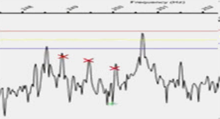
- Phase angle: Is a measure of the time delay between the voltage applied to the motor and the resulting current draw. It is a highly sensitive measurement and is one of the first variables to change when the insulation system begins to degrade. The Fi measurement is used to identify developing coil-to-coil, turn-to-turn or phase-to-phase winding faults. No other instrument can determine developing coil to coil winding faults at this stage.
- Current frequency response: The I/F response test measures the current through the motor windings at a predetermined frequency. A subsequent test measures the current response again at double that initial frequency. The I/F response measures the percentage change in the current caused by doubling the frequency of the input voltage. Three-phase winding in the same condition will respond the same to the change in frequency. If the winding insulation on one or more of the conductors begins to degrade it changes the ability of the coil to store a magnetic field or an electrical charge. The I/F is the test that measures the ability of a winding system to store a magnetic field or electrical charge and is generally one of the first indicators of winding system degradation.
- Dynamic Test: The dynamic test is used to identify developing or existing faults in the stator or rotor. During the dynamic test, the testing instrument continually measures and stores the impedance at different rotor positions while the motor shaft is manually rotated smoothly and slowly. The results of these tests are analyzed and displayed as two electrical signatures, the dynamic stator signature, and the dynamic rotor signature. The instrument then automatically analyzes these signatures and produces a “good,” “warn” or “bad” status to indicate the condition of the stator or rotor.
- Dissipation Factor (DF): The groundwall insulation system forms a natural capacitor between the conductors in the motor coils and the motor frame. A capacitor stores an electrical charge, when an AC voltage is applied to a capacitor part of the current flows across the dielectric material and is the resistive current (Ir) and the remainder of the current is the current that is stored. The stored current is referred to as capacitive current (Ic). On new insulation system the Ir is < 5% of the Ic. The DF is the ratio of the Ir /Ic. When the insulation material ages it becomes less capacitive and more resistive which causes the DF to increase.
- Capacitance to Ground (CTG): Since the groundwall insulation system forms a natural capacitance with the frame there will be a measurable value which should remain the same throughout the life of the motor. Moisture ingression or other contaminates effectively causes the dielectric constant to change. This generally causes the CTG value to go up. However, if the groundwall insulation begins to grade thermally it will cause the CTG to go down.
Summary: Combining the DF & CTG measurements provides a better indication of the overall condition of the groundwall insulation than IRG measurements alone. A standard IRG test will only detect ground failures at the weakest part of the winding’s insulation. DF and CTC tests will provide a complete assessment of the entire insulation system by using AC low voltage test methods. Combining these two tests with a IRG test will give you the most accurate condition of your motor’s insulation system to ground.
Traditional Testing Methods
Insulation Resistance to Ground (IRG) – This is a safety test & is not used to determine the actual condition of an electrical motor.
The insulation resistance to ground test are the most common electrical tests performed in the electrical field. The main purpose of these measurements is “safety”. When there is a path for current to flow from the energized winding to the casing of the machine or earth, it is possible that an exposed portion of the motor could become energized to the full voltage applied to the winding. Additionally, if sufficient current flows to ground it will create localized heating that could result in damage to plant as well as personnel. Prior to energizing a newly installed electrical systems an IRG test should be performed to ensure that the motor is “safe” to energize. The IRG test applies a DC voltage to the motor leads and measures the current flow to ground. Since current takes the path of least resistance this test identifies the weakest points of the groundwall insulation but does not provide any indication of the overall condition of the groundwall insulation.
Protect Against Insulation Failure with Equipment from ALL-TEST Pro
ALL-TEST Pro dependable motor testing products give your business the tools it needs to evaluate electrical performance and resolve minor issues quickly before they grow into more time-intensive and labor-intensive problems.
Why test motors? A well-maintained, high-performing motor is key to keeping your business running effectively, minimizing downtime, and boosting productivity and profits. ALL-TEST Pro can provide your business just that. Our testing, troubleshooting and predictive maintenance programs keep your motors running strong and providing high value for your company.