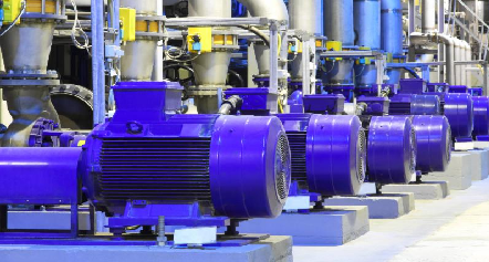
The fault diagnosis of induction motors, being probably the most common drivers used for industrial machinery plays an important role to reduce the catastrophic failures and production lost tonnage.
The detection of possible defects is usually not a rocket science, however very important step in identifying electrical problems on AC motors is to verify that the vibration is, in fact, electrical in nature and not a mechanical problem such as unbalance or misalignment.
These “electrical” problems can be divided into rotor or stator related problems, and are easily distinguished by their individual vibration characteristics.
Typical rotor problems could be cracked or broken rotor bars, or rotor eccentricity while typical stator problems are example stator eccentricity, shorted laminations or loose connections.
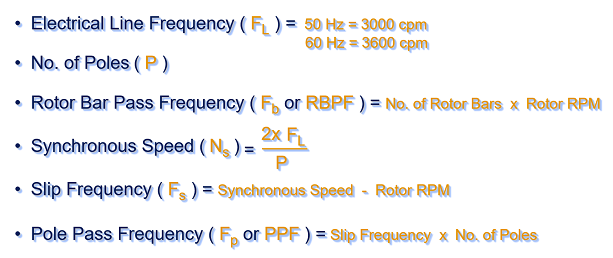
Before looking at AC motor defects, it is necessary to understand which are the most common frequencies produced by electrical motors and how these are calculated.
Let’s look deeper.
Since the magnetic field is induced through the rotor across an air gap, some energy will always be lost and the rotor simply could not keep up with the speed of the rotating magnetic field. As a result of this, induction motors will always have a slip frequency, which is the difference between the speed of the rotating magnetic field and the actual rotating speed of the rotor.
For example, the rotating speed of the magnetic field in a 2-pole motor is exactly AC line frequency (50 Hz) or 3000 cpm. If the rotor was turning at a speed of 2975 rpm, the slip frequency would be 25 cpm. Similarly, with a 4-pole motor, the magnetic field rotates at exactly half of AC line frequency or 1500 cpm. Therefore, if a 4-pole motor was actually running at 1480 rpm, the slip frequency would be 20 cpm.
Knowing the slip frequency the pole pass frequency (FP or PPF), which can be often observed while electrical faults, to be calculated.
To finish, however one more information to be required to calculate FP… the number of poles.
Where can we find that information? How to calculate it?
To determine the number of poles the motor nameplate information to be available as a minimum. Then if available, the motor running speed to be read and rounded up to the nearest 100, example:
2975 rpm >> 3000 rpm,
1480 rpm >> 1500 rpm.
With that round numbers the poles (P) can be calculated quite easily using the equation for the synchronous speed (Ns).
If the synchronous speed is 3000 rpm, the number of poles will be 2. In details:
NS = 2x FL / P >> P = 2x FL / NS
Number of poles = 2x 3000 cpm / 3000 cpm = 2.
Similarly, if a 4-pole motor, then synchronous speed will be 1500 rpm, etc.
Having all data now, the pole pass frequency is equal to the number of poles multiplied by the slip frequency. Using the previous example, a 2-pole motor operating at 2975 rpm will have a slip frequency of 25 cpm and the pole pass frequency would be 50 cpm (25 cpm x 2 poles = 50 cpm). Similarly, a 4-pole motor operating at 1480 rpm would have a slip frequency of 20 cpm and a pole pass frequency of 80 cpm (20 cpm x 4 poles = 80 cpm).
Furthermore to above, the most common frequencies that indicate electrical problems in AC motors are line frequency and twice line frequency (2x FL). In the Europe, most line frequencies are 50 Hz or 3000 cpm. In North America example, the line frequency is commonly 60 Hz or 3600 cpm. Then analogically 2x FL in Europe will be 100 Hz or 6000 cpm and in North America – 120 Hz or 7200 cpm.
With all that details how the electrical frequencies are calculated different AC motor faults to be analyzed.
One more thing before any spectra analysis is to ensure the data are always collected in a proper way.
Experience based, when testing motor for possible electrical problems it is recommended that the motor should be operating under a load to ensure the magnetic strength of the field. The commonly accepted practice is that the motor should be operating of at least 75% of its maximum rated load. If the motor is operating completely on its own, so not driving other component (gearbox, pump, etc) it does not usually have sufficient magnetic field strength to show potentially serious electrical problems.
Moreover some electrical problems may not appear on initial start-up when the motor is running cold. Problems such as cracked or broken rotor bars, or loose connections, may only show up after the motor reached its operating temperature and thermal expansion took place.
Very important is also to know that to pinpoint specific electrical problems is not always possible using vibration itself. Other electrical and physical tests like MCE may be required, however let’s focus on vibrations only and faults that can be detected using these.
Last, but not least, considering the previous examples and all written about most common frequencies produced by electrical motors, in a normal routine condition monitoring program, the resolution of the spectrum to be high enough to separate these frequencies. Whenever an analysis of an induction motor is to be done, it is recommended that an additional spectrum should be collected using a frequency range of 12 000 cpm with at least 3200 lines of resolution (if available 6400 lines is recommended). This setting will give a resolution of 3,75 cpm / line and this will make it possible to separate and clearly distinguish between mechanical and electrical vibration frequencies.
Summarizing, the faults patterns consist of the common frequencies produced by electrical motors and can be divided into stator or rotor related problems.
These electrical problems are distinguished by their individual vibration characteristics and as that to be analyzed.
The most typical AC motor faults patterns are:
Stator eccentricity, shorted laminations and loose iron
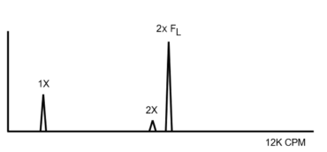
- High amplitudes at 2x FL (2x line frequency),
- Very directional vibration due to uneven stationary air gap,
note: for induction motors the differential air gap should not exceed 5%,
- Stator eccentricity can be due to soft foot,
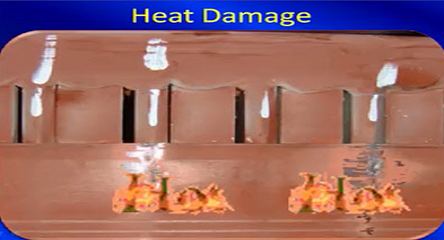
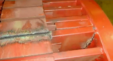
- Shorted stator laminations can cause uneven, localized heating which grows with operating time,
- Loose iron is due to stator support weakness or looseness.
Eccentric Rotor
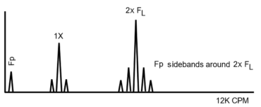
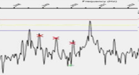
- Sidebands spaced at pole pass frequency (FP) above and below the 2x FL,
- Analysis often requires “zoom” spectrum to separate 2x FL and running speed harmonic,
- Pole pass frequency appears itself at low frequency,
- Common values of pole pass frequency range from approximately 20 to 120 CPM (see the calculation examples above).
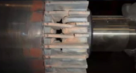
Rotor Problems
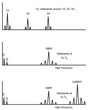
- Rotor bars problems can cause vibration at 1X, 2X and 3X rpm with pole pass frequency (FP) sidebands,
- Cracked rotor bars often will generate pole pass frequency (FP) sidebands around the 3X, 4X and 5X,
- Analysis often requires “zoom” spectrum to confirm pole pass frequency (FP) sidebands around 1X rpm and its harmonics,
- Loose rotor bars generate sidebands spaced at 2x FL above and below the RBPF and 2x RBPF,
- Loose rotor bars often will generate high levels at 2x RBPF, with only a small amplitude at 1x RBPF.
Phasing problems (loose or broken connectors)
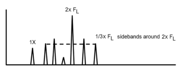
- Phasing problems can cause high vibration at 2x FL along with 1/3 FL sidebands,
- If defective connector, excessive amplitudes can be even up to 25 mm/s.


Pawel Lecinski ! Excellent article
Thank you so much for your kind words Rao Vamsidhar !
One thing that I have noticed and haven’t yet found an answer is, why are 2 pole motors far more prone to displaying high levels of 2xLF than 4, 6, 8, etc. pole motors? I was wondering if there is anybody in this community that could enlighten me on this.
Perhaps because in 2pole motors at the moment of switching the magnetic field, the motor must already make a half turn which is a change of 180 ° and the reason generating enormous forces.
Hello ,
Could you please help on the following situation :
AC motor 2952rpm / 50hz
high radial amplitude at 765 hz with a discontinuous noise , what could be the source of this deffect ?