Vibration, electrical and current signature analysis are technologies that can provide a great deal of information on the condition of our electric machines. In this case study an 1800 RPM, 715 RPM, 4000-volt vertical electric motor originally was operated across-the-line as shown in Figure 1. In 2021, the motor was found to have broken rotor bars which were replaced. The machine was retested in 2022 following the repair and was found in good condition with some level of rotor brazing issues as shown in Figure 2.
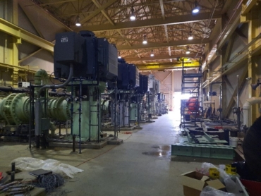
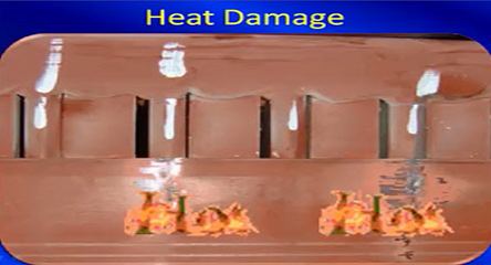
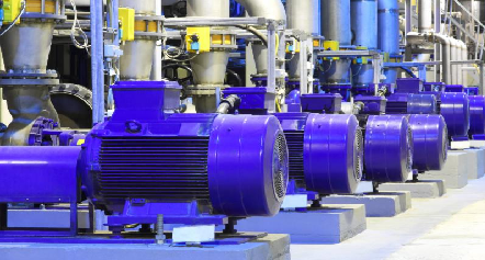
Figure 1: Vertical Pump Motors
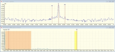
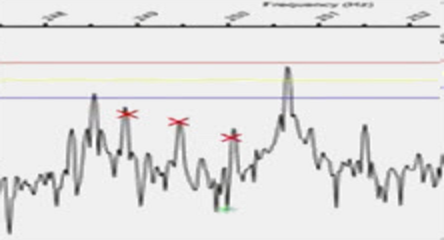
Figure 2: Post rotor repair brazing PPF peaks.
The following year the motor control was converted from across-the-line to medium voltage VFD as shown in Figure 3. Vibration analysis identified a potential rotor bar issue, so it was determined to evaluate with Electrical Signature and Current Signature Analysis (ESA/MCSA).
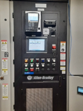
Figure 3: Variable Frequency Drive installed, ESA/MCSA connected back of relay.
An EMPATH ESA was performed using the back of the relay with current results showing in Figure 4. This shows as a classic Pole Pass Frequency (PPF) around line frequency with harmonics and other signatures including current oscillation showing as potential multiple rotor bars.
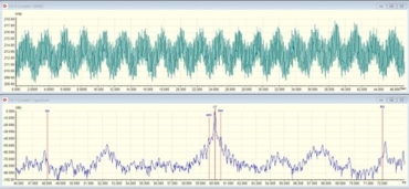
Figure 4: ESA current oscillation and PPF sidebands with harmonics.
We determined that the next step would be to evaluate voltage as shown in Figure 5.
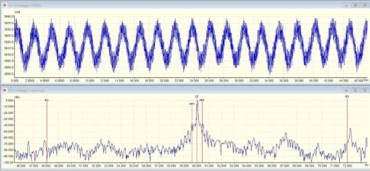
Figure 5: Voltage signature with oscillation and the same sidebands.
Figure 6 is current only with an EMPOWER MCSA system showing a slightly different version of sidebands in which the first sideband peaks have harmonics that are half the PPF, which would be an indicator of a challenge other than rotor bars.
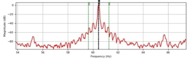
Figure 6: The higher resolution current provides a better view of the peaks indicating that the sidebands are half PPF.
One of the settings on the VFD is ‘gain.’ In this case the gain was set to high, and the sidebands are the result of rapidly varying changes in frequency. These changes are based upon the VFD reacting too rapidly to small variations in pump flow.
The PPF is a common signature for the detection of rotor bars. Paying attention to the condition and results of the data allows you to verify whether or not it is rotor bars or something else such as controls.
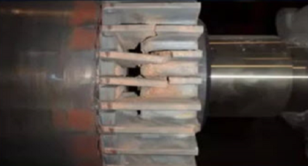
A second 4700 hp, 1188 RPM, 4000 Volt wound rotor motor on a rotary kiln with a 38-gear pinion and 318 gears on the kiln. A service company using an alternate ESA system identified potential rotor issues at which point the EMPATH was employed to evaluate the motor rotor and gear conditions. As seen in Figure 7, the PPF and gear issues are roughly the same. However, the current oscillation is not consistent with the regular pattern of a rotor condition, so an inspection of the gears was performed, and wear and damage were found to be consistent with the type of signature found.

Figure 7: Gearbox issue appears similar to PPF rotor bars.
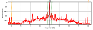
Figure 8: EMPOWER data showing peaks associated with gearbox and PPF.
Just as with any CBM technology, understanding the full context of the equipment being operated is key to ensuring that correct calls are made, especially when considering rotor and rotor bar conditions. In these two case studies, one was a control condition and the second was a gearbox condition in which the problems emulated rotor defects.